


Views: 263 Author: CNDY-Press Publish Time: 2026-10-11 Origin: Site


Content Menu
● 1. Choose the Right Press Brake Bending Method
>> Air Bending Is a Practical Starting Point
>> Do Not Use Universal Force Multipliers
● 2. Select Tooling Around the Material and Drawing
>> Treat the Rule of Eight as a Starting Point
>> Understand the Natural Inside Radius
>> Inspect Tooling Before Programming Corrections
● 3. Calculate Bending Force With Clear Units
● 4. Measure Material Instead of Trusting Nominal Thickness
>> Define Grain Direction Unambiguously
>> Use Grade-Specific Minimum Radii
● 5. Compensate for Springback Through Test Bends
● 6. Separate Crowning, Ram Correction, and Backgauge Adjustment
>> Crowning Corrects Lengthwise Deflection
>> Ram Corrections Address Overall Angle
>> Backgauge Corrections Address Positioning
● 7. Use a Controlled First-Off Approval Process
>> Preserve More Than the CNC Program
● 8. Diagnose Bending Defects Before Adjusting Settings
● 9. Prevent Handling Problems and Collisions
>> Review the Entire Bend Sequence
>> Slower Speed Does Not Replace Safeguarding
● 10. Maintain Accuracy Through Documented Inspection
● Specify a CNC Press Brake Around Real Production Requirements
>> 1. Why does the same CNC program produce different angles?
>> 2. Is an eight-times-thickness V-opening always correct?
>> 3. Can dwell time eliminate springback?
>> 4. Why is the center angle different from the ends?
>> 5. Should I bend parallel or perpendicular to the grain?
Effective press brake tips and tricks start with controlling the variables that determine precision sheet metal bending: material properties, tooling geometry, machine condition, and the measurement method. A CNC press brake can repeat a programmed position accurately, yet still produce inconsistent parts when incoming material or setup conditions change.
For manufacturers, the objective is not simply an acceptable first bend. It is a stable process that produces conforming parts throughout the batch, with predictable setup time and limited rework.
My recommended approach is control: establish a verified setup, measure the unloaded part, change one variable at a time, and record the result.

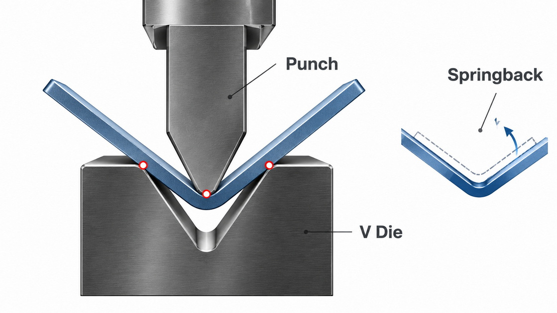
Air bending, bottom bending, and coining use different forming conditions. They should not share an assumed force requirement or correction strategy.
| Method | How it works | Main advantage | Main limitation |
|---|---|---|---|
| Air bending | Sheet contacts the punch and two die shoulders | Flexible angles with relatively low force | Sensitive to material and penetration changes |
| Bottom bending | Sheet is brought into close contact with matched tooling | Can provide repeatable results in a validated setup | Higher force and more specific tooling |
| Coining | High pressure plastically deforms material into the tooling geometry | Strong geometric control | High loading and limited flexibility |
Air bending is widely used because the angle can be adjusted through punch penetration rather than changing tooling for every target angle.
However, penetration alone does not determine the final result. Thickness, strength, grain orientation, die opening, and springback also matter.
Bottoming and coining generally require more force than air bending, but fixed multipliers are not reliable for every job.
Use the machine and tooling suppliers' data for the actual process. A press brake with sufficient total capacity may still overload a short punch segment or concentrated section of the bed.
A V-die opening around eight times sheet thickness is a familiar guideline for some mild-steel air-bending applications. WILA describes a starting range of approximately six to eight times thickness for relevant thin-steel work.
It is not a universal rule for stainless steel, aluminum, high-strength steel, or thick plate.
Changing the opening affects:
- Required forming force.
- Natural inside radius.
- Minimum achievable flange.
- Surface marking.
- Flat-pattern development.
Check all five before substituting a die.
In air bending, the punch nose does not automatically define the finished radius.
For common mild-steel conditions, an inside radius near 16% of the V-opening is a published starting estimate. Material properties and the forming geometry can change that relationship.
If the drawing requires a controlled radius, verify it on the formed sample rather than assuming that a punch marked with that radius will produce it.
Clean contact surfaces and inspect punches, dies, and clamps for damage or contamination.
Debris under a die can create a local alignment problem. A worn or damaged tool can create marks or inconsistent forming that software offsets cannot reliably resolve.
Use only approved cleaning, lubrication, and installation procedures. Do not add unapproved shims or modify load-bearing tooling interfaces.
A useful imperial estimate for conventional air bending is:
Tper foot=575t2/V×UTS/60,000
Where:
- Tper foot is US short tons per foot of bend.
- t is thickness in inches.
- V is die opening in inches.
- UTS is ultimate tensile strength in psi.
Multiply by bend length in feet to estimate total force.
This is an estimate for the stated air-bending conditions—not a substitute for a supplier's capacity chart or a formula for offset tooling, bottoming, or coining.
Before forming, verify:
1. Total machine capacity.
2. Permitted concentrated loading.
3. Punch and die load ratings.
4. Clamp and adapter limits.
5. The manufacturer's permitted loading position.
Thickness is squared in the estimate. Consequently, a small thickness increase can create a meaningful force increase.
Always distinguish US short tons from metric tonnes-force. Mixing them can produce an incorrect capacity comparison.
Measure representative blanks with an appropriate calibrated instrument. Record the material grade, thickness, batch identity, and surface condition.
For demanding work, compare the material certificate with the purchase specification.
Two batches sold under the same grade can require different corrections because their mechanical properties differ within the allowed specification.
Specify the orientation of the bend line relative to the rolling direction.
For many rolled materials, a bend line parallel to the grain increases cracking risk, especially at a tight radius. A transverse bend line is generally more favorable for crack resistance.
Do not use vague instructions such as "bend with the grain" without a sketch or written orientation.
There is no universal minimum radius for all aluminum or steel.
Alloy, temper, strength, thickness, edge condition, and orientation affect bendability. Consult the material supplier's guidance and validate the selected radius before production.
Springback is the elastic recovery that occurs after forming pressure is released.
It varies with material properties, thickness, radius, orientation, and process conditions. Fixed compensation values such as "two degrees for aluminum" are not reliable production settings.
Measure after release, at defined locations, using a consistent angle convention.
For an illustrative target of a 90° included angle, a validated process might need an 88° loaded angle if the part opens by 2°. That example is not a recommended setting for an unspecified material.
A dwell may help the machine reach a repeatable forming condition in some applications. It does not remove elastic recovery or compensate for incorrect tooling.
Evaluate dwell changes through controlled trials and the machine manufacturer's guidance. Increasing dwell without evidence can add cycle time without improving the part.
These adjustments address different problems.
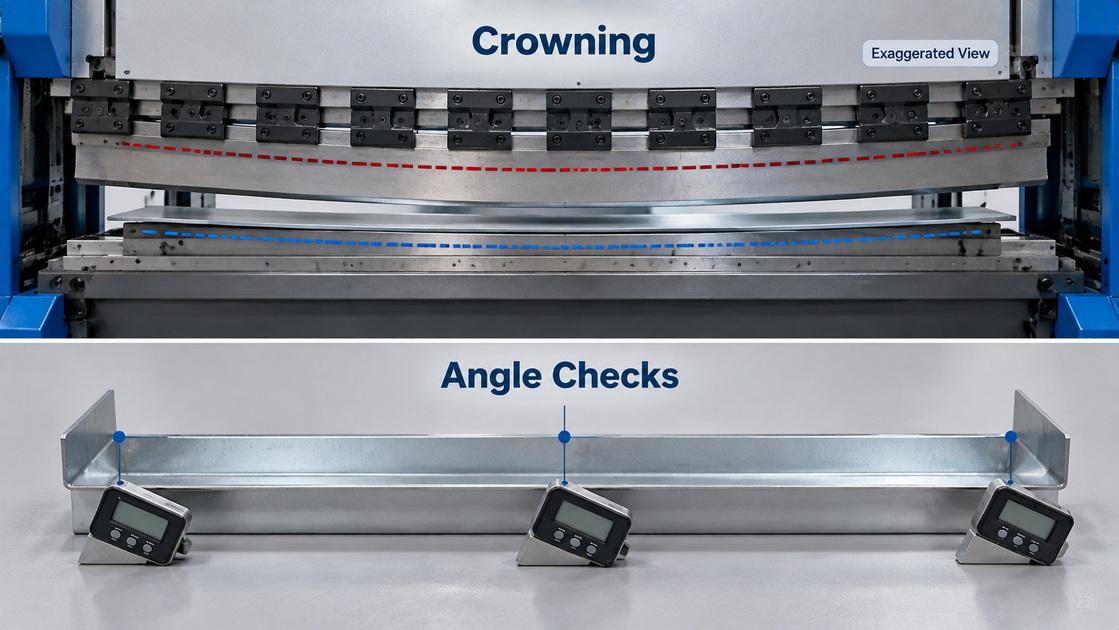
During bending, the ram and bed deflect under load. Crowning compensates for that deformation to improve consistency along the bend.
Measure the unloaded angle near both ends and the center. A repeatable center-to-end difference can indicate a compensation issue, although tooling seating and material variation should also be checked.
Use the approved crowning procedure for the machine. One system's settings should not be copied to a different model.
If the bend is consistently too open or too closed along its length, investigate material data, tool selection, and the programmed angle or penetration correction.
Do not use crowning to fix an essentially uniform angle error.
A backgauge determines where the blank is located relative to the bend line.
Check finger alignment, the selected datum, and contact with the correct edge. Moving the backgauge is not the appropriate first response to a springback problem.
Also confirm angle before diagnosing flange dimensions: angle variation can affect how those dimensions are measured.
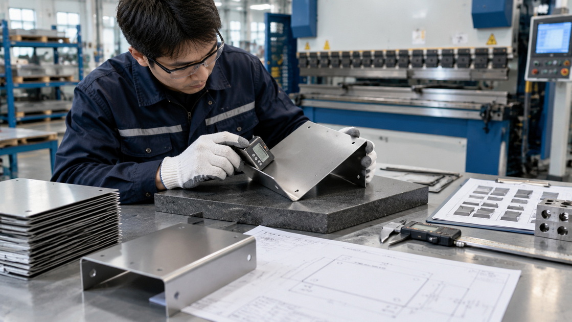
A repeatable first-off routine is more useful than accumulated undocumented operator corrections.
1. Confirm the drawing revision and tolerances.
2. Identify material grade, thickness, and rolling direction.
3. Verify tooling geometry and load ratings.
4. Check setup and machine condition under approved procedures.
5. Review the bend sequence for interference.
6. Form a representative test part.
7. Measure angle, flange dimensions, radius, and visible defects.
8. Change one relevant variable at a time.
9. Record the accepted settings and sample results.
Check additional parts at defined intervals. Repeat approval after a material-lot change, tool replacement, or significant setup change.
Store tool identities, machine identity, material details, orientation, inspection points, and correction history.
An old program can reproduce old axis positions without reproducing the old part if the supporting conditions have changed.
| Observed problem | Initial checks | Adjustment caution |
|---|---|---|
| Uniform angle error | Material, tool data, unloaded measurement | Do not begin with crowning |
| Center differs from ends | Deflection compensation, tool seating | Do not mask it with a global offset |
| Incorrect flange length | Datum, blank size, gauge contact, angle | Verify measurement geometry first |
| Cracks along bend | Radius, grain orientation, grade, edges | More force is not a cure |
| Surface marks | Tool condition, debris, contact pressure | Validate any protective film |
| Batch-to-batch drift | Thickness, strength, lot identity | Do not accumulate unexplained offsets |
This table is a diagnostic starting point, not proof of a single cause.
If the required correction grows over time, investigate the underlying change rather than continually modifying the program.
The final geometry does not show every intermediate collision.
Check punch clearance, sidewalls, backgauge fingers, part rotation, and removal paths. Offline simulation can identify risks, but it must use accurate tooling and machine data.
Verify the physical setup through the manufacturer's approved procedure.
Reducing speed can help control part movement in some operations, but it does not make unsupported handling safe.
Large panels may rotate or create trapping hazards. Use suitable supports, handling equipment, and qualified staffing based on a risk assessment.
Keep hands outside hazardous areas. Never bypass protective devices to complete a difficult bend.
OSHA identifies point-of-operation safeguarding as essential for powered press brakes. Follow the applicable local requirements and machine-specific instructions.
Maintenance intervals should come from the machine manufacturer, operating conditions, and condition monitoring—not a universal hour count.
A useful inspection system covers:
- Approved checks of safeguards.
- Tooling and clamp condition.
- Hydraulic leaks and fluid condition.
- Backgauge positioning.
- Ram synchronization where applicable.
- Crowning function.
- Measurement-equipment calibration.
Use authorized personnel and required energy-isolation procedures for servicing.
Maintain records so recurring drift can be distinguished from an isolated setup error.
For CNDY-Press, an effective OEM or ODM discussion should begin with representative parts rather than nominal tonnage alone.
Provide material grades, thickness range, maximum bend length, required tolerances, batch sizes, and difficult geometries. Include requirements for tooling, backgauge axes, angle measurement, supports, automation, and safeguarding.
Request an acceptance plan using agreed parts and inspection criteria. This creates a clearer basis for customization than a broad promise of "high precision."
Precision depends on a controlled relationship between material, tooling, machine behavior, and inspection.
Start with verified tooling and capacity. Measure released parts, distinguish positioning errors from angle errors, and preserve accepted setup information.
Material thickness, strength, orientation, tool condition, and setup can change. Compare those variables before assuming the controller is inaccurate.
No. It is a starting guideline for certain air-bending conditions. Verify radius, flange length, material formability, force, and tooling limits.
No. Dwell may influence process repeatability, but elastic recovery remains material- and geometry-dependent. Validate its effect instead of assuming longer is better.
Possible causes include load-induced deflection, crowning settings, tool seating, and uneven material conditions. Measure a consistent pattern before changing compensation.
For many rolled materials, a transverse bend line is less prone to cracking. Use grade-specific guidance and define orientation clearly.
1. [CNHAWE — Press Brake Tips and Tricks for Precision Sheet Metal Bending]
Original article supplied for restructuring. Its broad springback ranges, grain-direction advice, radius guidance, dwell explanation, and fixed maintenance intervals were reassessed rather than reproduced as universal rules. No identifiable reader comments were available in the retrieved content. [cnhawe]
2. [WILA — V-Opening] and [Air Bending]
Tooling-manufacturer guidance supporting application-dependent V-openings and their effects on radius, force, marking, flange length, and flat patterns. [wilatooling]
3. [The Fabricator — The Rules of Press Brake Tool Selection]
Supports the rule-of-eight discussion and approximately 16% natural-radius estimate for common mild-steel air bending. These are starting estimates, not universal acceptance criteria. [thefabricator]
4. [The Fabricator — Press Brake Basics: Material, Die Width, and Bending Force]
Corrected October 2026 explanation of the imperial air-bending force estimate, tensile-strength adjustment, thickness-squared relationship, and conversion from force per foot to total force. [thefabricator]
5. [The Fabricator — Grain Direction's Effect on Sheet Metal Bending]
Supports the distinction between bend lines parallel and transverse to rolling direction and the associated crack-risk guidance. [thefabricator]
6. [The Fabricator — Grain Size, Part I: Material Grain Size Matters in Sheet Metal Bending]
Additional guidance on grain orientation, minimum radii, and material-dependent forming behavior. [thefabricator]
7. [The Fabricator — Bending Basics: The Hows and Whys of Springback and Springforward]
Supports the explanation of elastic recovery and the influence of thickness, grain direction, strength, and radius. [thefabricator]
8. [WILA — How to Compensate for Deflection of a Press Brake]
Supports load-induced deflection, crowning, and the need for compensation matched to the machine. [wilatooling]
9. [The Fabricator — How to Reduce Press Brake Setup Times]
Supports documenting tooling identities, geometry, lengths, and load ratings for repeatable setups. [thefabricator]
10. [OSHA — Powered Press Brakes] and [Machine Guarding: Presses]
Official safety guidance supporting safeguarding and energy-isolation considerations. This article does not replace a machine-specific risk assessment or applicable legal requirements. [osha]


