


Views: 240 Author: CNDY-Press Publish Time: 2026-10-14 Origin: Site


Content Menu
● Start with the Machine Configuration, Not a Generic Checklist
● Press Brake Maintenance Safety: Isolation Comes First
● A Practical CNC Press Brake Maintenance Schedule
● Hydraulic Press Brake Maintenance: Manage Fluid Condition
>> Appearance Is Not a Reliable Oil Analysis
>> Do Not Replace Oil Solely Because Another Year Has Passed
>> Treat Leaks as a Safety and Reliability Issue
● Press Brake Troubleshooting: Preserve the Fault Before Resetting
● Common Press Brake Problems and Safe First Responses
● Distinguish Bend-Angle Errors from Backgauge Errors
● An Overlooked Trap: Using Compensation to Hide Deterioration
● Condition Monitoring Without Overpromising Prediction
● CNC Backups and Software Changes
● Return-to-Service Verification After Maintenance
● Build a Useful Service Request for CNDY-Press
>> 1. Must Hydraulic Oil Be Changed Every Year?
>> 2. Is an Emergency Stop Enough Before Maintenance?
>> 3. Can Operators Adjust Hydraulic Pressure to Correct Weak Bending?
>> 4. Should Worn Press Brake Tools Be Sharpened?
>> 5. Is Compressed Air Suitable for Cleaning Electrical Cabinets?
Effective press brake maintenance and troubleshooting begins with a clear distinction: operators identify abnormal conditions, while qualified personnel investigate faults and perform repairs within their authorization. A checklist alone cannot replace the machine manual, an energy-control procedure, or application-specific safeguarding.
For CNC press brakes, maintenance must address more than hydraulic oil and lubrication. Tooling, backgauges, position feedback, electrical systems, software configuration, and safety functions all influence reliable production.
At CNDY-Press, our business includes developing, manufacturing, selling, and servicing press brakes and related sheet metal equipment, with OEM and ODM customization. From a maintenance-planning perspective, I would prioritize evidence: record what changed, preserve fault information, and verify the result before returning the machine to production.
This guide provides a practical framework for preventive maintenance, symptom-based troubleshooting, and service preparation. It is not a repair procedure for a particular machine.

Different press brakes have different service requirements.
| Machine configuration | Maintenance priorities | Important limitation |
|---|---|---|
| Hydraulic | Fluid condition, filtration, hoses, cylinders, valves, cooling | Oil specifications and service intervals are machine-specific |
| Servo-hydraulic or hybrid | Hydraulic components plus associated drives and controls | Reduced oil volume does not eliminate hydraulic maintenance |
| Servo-electric | Actual drive mechanism, lubrication, feedback, electrical components | Not every electric press brake uses ball screws |
| Older mechanical | Clutch, brake, transmission, lubrication, safeguarding | Requires design-specific expertise |
| Robotic bending cell | Press brake plus robot, grippers, handling, integrated safety | Cell-level hazards extend beyond the machine |
Record the serial number, controller version, installed options, drawings, and service documentation.
A useful maintenance plan follows the installed equipment—not assumptions about what a "standard" press brake contains.
Switching off the control screen or pressing an emergency stop does not establish energy isolation.
Before servicing where unexpected movement or energy release could cause injury, authorized personnel must follow the applicable machine-specific lockout/tagout procedure.
Relevant hazards may include:
- Electrical energy.
- Hydraulic pressure.
- Pneumatic pressure.
- Gravity and a raised ram.
- Stored mechanical energy.
- Connected handling equipment.
Stored energy must be controlled, and isolation verified before work begins. Where energy can reaccumulate, continued verification may be necessary.
Ram restraint, pressure release, and electrical verification require approved procedures and suitable equipment. Do not improvise supports or assume that a stationary ram cannot descend.
Operational checks and energized diagnostics require their own controlled procedures. They should not be casually mixed with isolated maintenance work.
The following table is a planning framework. The manufacturer's instructions, operating hours, environment, and applicable requirements determine actual tasks and intervals.
| Review point | Suggested focus | Responsibility |
|---|---|---|
| Before each shift | Visible condition, tooling, leaks, alarms, approved safety checks | Trained operator within authorization |
| Scheduled routine review | Lubrication delivery, accessible contamination, filter indicators, abnormal trends | Assigned maintenance personnel |
| Periodic technical service | Mechanical condition, fluid analysis, feedback, clamping, approved accuracy checks | Qualified technician |
| After a collision or serious fault | Damage assessment and documented verification | Authorized service personnel |
| After repair or configuration change | Relevant functional, safety, and production checks | Designated competent personnel |
Inspect the machine and work area without entering hazardous zones.
Look for damaged tooling, loose or missing components, visible leaks, unusual contamination, and unresolved alarms. Check lubricant or fluid indications only under the conditions prescribed by the manual.
Conduct safety-function checks using the approved procedure. Never test a protective device by placing a body part in danger.
A production test bend can help verify the job setup. It does not prove complete machine calibration or safety compliance.
Follow specified lubricant types, quantities, and intervals.
Check whether automatic lubrication is actually delivering lubricant—not merely whether its reservoir contains fluid.
Keep approved contact surfaces and tooling seats clean. Inspect storage and handling practices that could damage precision tools.
Do not tighten every fastener indiscriminately. Follow specified torque values and service instructions.
Plan deeper inspections around operating conditions and documented requirements.
Possible tasks include fluid sampling, wear assessment, positioning verification, cooling-system inspection, and control backups.
Avoid turning this into an automatic overhaul schedule. Tank cleaning, bearing replacement, seal replacement, and oil changes should follow applicable instructions and condition findings.
Clear-looking hydraulic fluid can still contain harmful particles, water, or degraded constituents.
Useful laboratory measurements can include:
- Particle count.
- Water content.
- Viscosity.
- Acid or neutralization number.
- Wear metals.
Use limits appropriate to the installed components and fluid. Do not assign one cleanliness target to every press brake.
Trend comparable samples over time. Changing the sampling location or method can make results difficult to interpret.
Follow the manufacturer's required replacement interval. Where condition-based decisions are permitted, combine laboratory findings with operating history, contamination events, and temperature trends.
A calendar date alone cannot establish fluid suitability. Equally, a favorable analysis does not justify ignoring a mandatory service requirement.
Use the approved oil specification. Matching viscosity alone does not establish compatibility with seals, additives, or existing fluid.
Report visible leaks and damaged hoses. Do not search for pressurized leaks with your hands or tighten fittings while the system is energized.
High-pressure fluid injection is a medical emergency, even if the external wound appears small.
Repeated topping-up without investigating the loss can conceal a developing fault and introduce contamination.
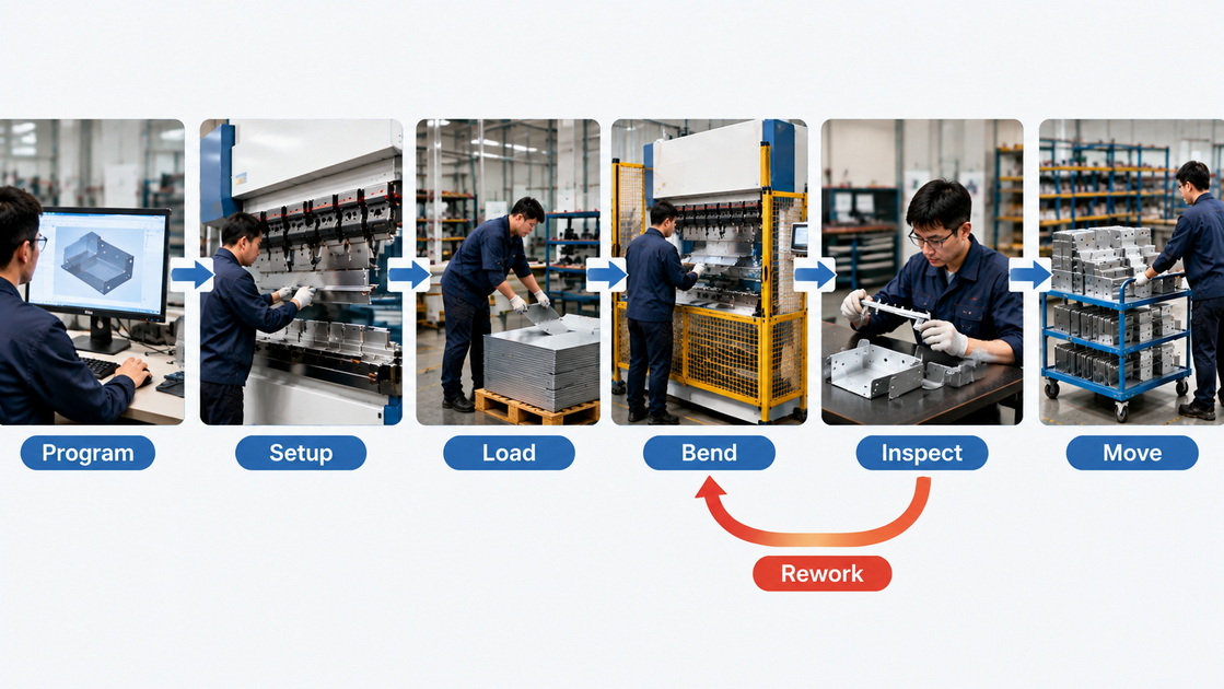
Repeated resets can erase useful evidence while leaving the cause unresolved.
When a fault occurs, record:
1. Exact alarm text and code.
2. Date, time, and operating state.
3. Program and part identification.
4. Material and tooling details.
5. Whether the problem began cold or after warming.
6. Recent maintenance or parameter changes.
7. Photographs or logs captured safely.
Do not deliberately reproduce uncontrolled movement, a suspected structural fault, or a safety-device failure.
A clear fault record helps service personnel distinguish process problems from machine faults.
| Symptom | Information to collect | Safe initial response | Escalation boundary |
|---|---|---|---|
| Inconsistent bend angle | Material, tooling, program, location of variation | Review approved setup and inspect accessible tooling | Machine alignment or control adjustment |
| Incorrect flange dimension | Measurement method, gauge command, contact condition | Check job data and approved positioning setup | Backgauge calibration or feedback repair |
| Ram does not respond | Alarm code and machine state | Follow the manual’s operator-level fault guidance | Electrical, hydraulic, or safety-circuit work |
| Unusual noise or heat | When it occurs and relevant readings | Stop according to procedure and report | Pump, bearing, drive, or cooling diagnosis |
| Visible hydraulic leak | Location observed from a safe distance | Restrict use and escalate | Pressure-system repair |
| Unexpected movement | Event details gathered safely | Stop use and secure the machine | Immediate qualified assessment |
This table identifies investigation paths, not repair instructions.
An angle problem and a flange-length problem may have different causes.
For inconsistent angles, investigate material variation, tooling condition, setup, and any relevant compensation functions.
For incorrect flange dimensions, investigate program values, how the blank contacts the gauge, measurement methods, and positioning performance.
A backgauge problem does not automatically explain an angle variation across a long bend. Similarly, changing crowning will not necessarily correct an incorrectly positioned bend line.
Use a controlled test with documented material and tooling. If approved process checks do not explain the error, involve service personnel before altering machine geometry or calibration.
Compensation functions can address expected process behavior. They should not become a substitute for investigating a sudden change.
If an established part starts requiring progressively larger corrections, record the trend.
Possible investigation areas include material batches, tooling, temperature, lubrication, positioning, and mechanical condition.
Changing several parameters simultaneously makes diagnosis harder. It may also leave an undocumented configuration that another operator cannot reproduce.
Maintain an approved baseline and a change log. Machine and safety parameters should be changed only by authorized personnel following the relevant procedure.
Start with a small set of useful observations:
- Alarm frequency.
- Oil temperature under comparable conditions.
- Cycle time for a reference job.
- Positioning deviations.
- Fluid-analysis trends.
- Repeated quality corrections.
Record operating context. A temperature increase during a heavier job is not directly comparable with a lighter baseline.
Condition monitoring can identify abnormal trends and support diagnosis. It does not automatically predict the exact remaining life of a pump, valve, or bearing.
Before adding complex monitoring, confirm that someone reviews the data and knows when to escalate it.
A program backup may not include everything needed to recover the machine.
Confirm whether the backup covers:
- Part programs.
- Tool libraries.
- Machine parameters.
- Calibration data.
- Controller configuration.
- Relevant drive or PLC information.
- Restoration instructions.
Store approved backups separately from the controller and identify their machine, date, and version.
Install updates only through a supported procedure. New software is not automatically compatible with every installed option.
Do not add general-purpose antivirus software or make network changes without controller-vendor approval. Cybersecurity measures must suit the supported industrial system.
Finishing a repair is not the same as approving production.
Define checks according to the work performed. These may include:
1. Inspection of repaired components.
2. Restoration of guards and connections.
3. Authorized release of energy controls.
4. Relevant safety-function verification.
5. Controlled operational checks.
6. First-part inspection.
7. Documented production authorization.
A successful bend alone cannot confirm that all affected safety functions operate correctly.
Record the replaced parts, configuration changes, test results, and person responsible for release.
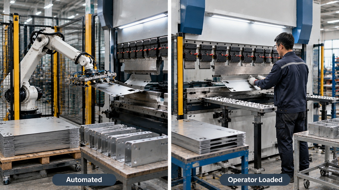
A detailed service request reduces avoidable back-and-forth.
Provide the machine identification, controller version, fault codes, operating conditions, relevant drawings, and recent change history. Include photographs only when they can be obtained safely.
For OEM and ODM projects, define maintenance needs during development:
- Access to service points.
- Available documentation.
- Replacement-component identification.
- Backup and recovery responsibilities.
- Training requirements.
- Spare-parts support.
- Service-response arrangements.
Custom equipment needs a custom service plan. Agree on the deliverables rather than assuming that standard documentation covers every modification.
Not universally. Follow the machine's required schedule and approved condition-monitoring approach. Oil analysis cannot override a mandatory manufacturer requirement.
No. It is not an energy-isolating device. Use the applicable lockout/tagout procedure, control stored energy, and verify isolation.
They should not make unauthorized pressure adjustments. Verify the job and report the symptoms. Pressure diagnosis and adjustment require qualified personnel and approved specifications.
Not as a generic maintenance task. Reconditioning can change geometry, hardness, and rated performance. Obtain tooling-manufacturer approval or replace unsuitable tools.
Do not assume so. Follow the equipment manufacturer's cleaning procedure and electrical-safety requirements. Cabinet work belongs to appropriately qualified personnel.
1. [CNHAWE — "The Ultimate Guide to Press Brake Maintenance and Troubleshooting," August 19, 2025]. Source article used to identify topics and information gaps. This reconstruction adds responsibility boundaries, stored-energy controls, evidence-based diagnosis, and return-to-service verification. It does not adopt blanket annual oil replacement, routine tooling sharpening, or generic cabinet-cleaning instructions. No user comments were visible in the retrieved content, and none were supplied separately; no testimonials have been invented. [cnhawe]
2. [OSHA — 29 CFR 1910.147: The Control of Hazardous Energy]. Official requirements supporting energy isolation, stored-energy control, verification, and inspection before release. Applicability depends on jurisdiction and work circumstances. [osha]
3. [OSHA — Lockout/Tagout: Energy-Control Procedures and Control-Circuitry Prohibition]. Supports the distinction between operating controls and energy-isolating devices. [osha]
4. [Parker Hannifin — The Handbook of Hydraulic Filtration]. Technical source for fluid contamination, limitations of visual assessment, laboratory measurements, and representative sampling. Sampling must follow the machine's approved safety procedure. [parker]
5. [Parker — Industrial Hydraulic Condition Monitoring]. Supports monitoring fluid contamination and its relationship to hydraulic-component reliability. [parker]
6. [TRUMPF — "Remote, Smart, and Proactive: Four TRUMPF Services of the Future"]. Manufacturer context for condition monitoring and diagnostics; its described services are not claimed as features of CNDY-Press equipment. [trumpf]


