


Views: 264 Author: CNDY-Press Publish Time: 2026-09-26 Origin: Site


Content Menu
● What Is a Press Brake Back Gauge and Why Does It Control Flange Accuracy?
● CNC Press Brake Back Gauge Axes Explained
● Common Press Brake Back Gauge Problems and Their Likely Causes
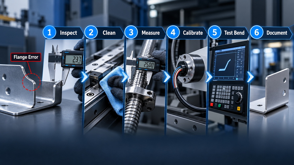
● Press Brake Back Gauge Troubleshooting: A Safe Seven-Step Process
>> 1. Define the Error Before Adjusting Anything
>> 2. Inspect the Workpiece and Tooling Reference
>> 3. Clean the Rails, Beam, Fingers, and Drive Area
>> 4. Check Mechanical Condition and Backlash
>> 5. Verify Homing, Encoder Feedback, and Axis Motion
>> 6. Measure Back Gauge Parallelism and Finger Position
>> 7. Test Bend, Measure, Document, and Recheck
● How to Calibrate a CNC Press Brake Back Gauge
>> When Should You Calibrate the Back Gauge?
>> Back Gauge Calibration Checklist
● Calibration vs. Repair vs. Retrofit: Which Solution Do You Need?
● When Is a Press Brake Back Gauge Retrofit Worth It?
>> What to Specify for a Custom Back Gauge Retrofit
● Preventive Maintenance That Protects Back Gauge Accuracy
● Restore Accuracy Before It Becomes Scrap
● FAQ
>> 1. What causes a press brake back gauge to lose accuracy?
>> 2. How often should I calibrate a CNC press brake back gauge?
>> 3. Why are the left and right flange dimensions different?
>> 4. Can I fix back gauge error by changing CNC offsets?
>> 5. Is a back gauge retrofit cheaper than buying a new press brake?
A CNC press brake can have the correct program, tooling, and operator—and still produce inconsistent flange dimensions if the back gauge positioning system is inaccurate. When parts drift by 0.5–2.0 mm, require repeated manual offsets, or vary from the left side of the bed to the right, the problem often originates in back gauge calibration, mechanical wear, encoder feedback, axis alignment, or an outdated control configuration.
For sheet metal manufacturers, inaccurate gauging creates a chain reaction: longer setup times, scrap, rework, missed delivery schedules, and operator frustration. From our experience supporting CNC press brake users in HVAC, electrical enclosures, automotive components, steel fabrication, and OEM production, the most productive approach is not to immediately replace a press brake. First, identify whether the problem is a calibration issue, a mechanical issue, an electrical-control issue, or a capacity limitation.
This guide explains how to troubleshoot a CNC press brake back gauge, calibrate common X, R, Z1, and Z2 axes, decide when a retrofit makes sense, and specify a customized CNDY-Press back gauge solution for OEM or ODM equipment projects.
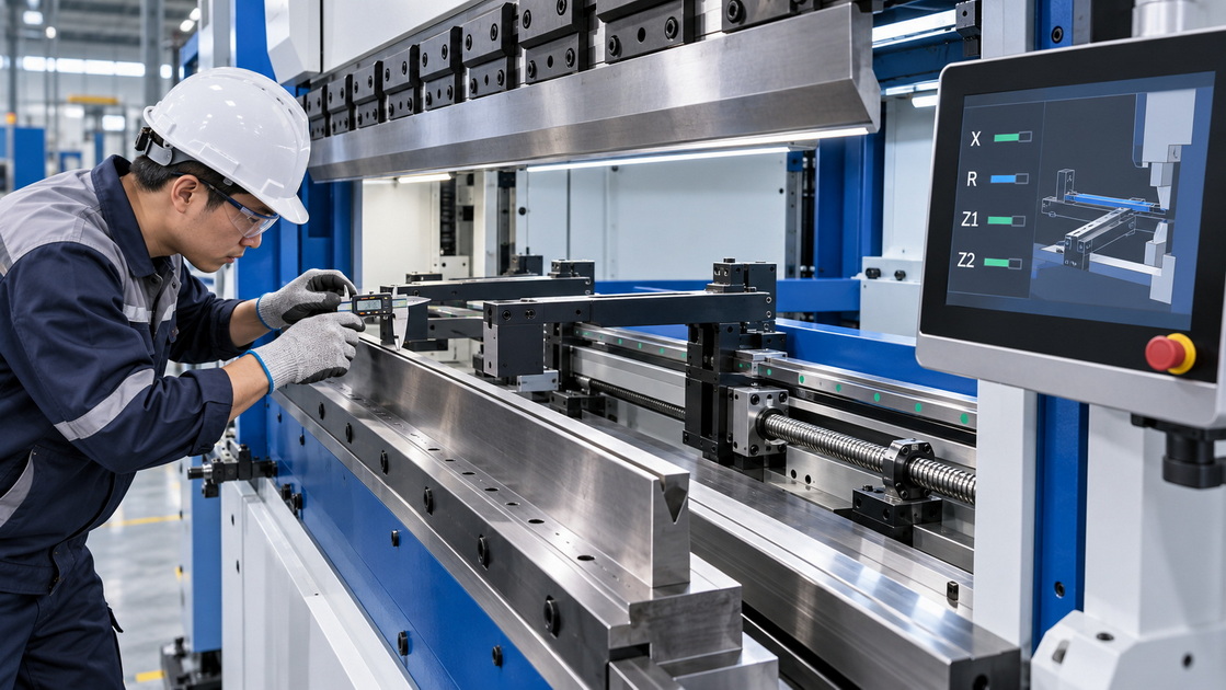
A press brake back gauge is the rear positioning system that establishes where a sheet-metal blank stops before bending. The operator pushes the material against the back gauge fingers; the distance between the stop point and the bending line determines the finished flange length.
In simple manual systems, operators set a physical stop with a handwheel, scale, or mechanical adjustment. In modern CNC press brakes, the controller automatically moves the gauge through programmed coordinates for every bend in a sequence.
The back gauge therefore affects more than one dimension. It influences:
- Flange depth and dimensional repeatability
- Setup time between bending programs
- Positioning consistency from part to part
- Operator dependence and manual adjustment
- Accuracy of multi-bend and box-forming sequences
- Output stability in long production batches
- Scrap and rework caused by incorrect bend references
A healthy back gauge gives every part the same positioning reference. An inaccurate one forces operators to compensate with offsets, manual corrections, or trial bends—actions that may temporarily produce an acceptable part while hiding the real equipment problem.
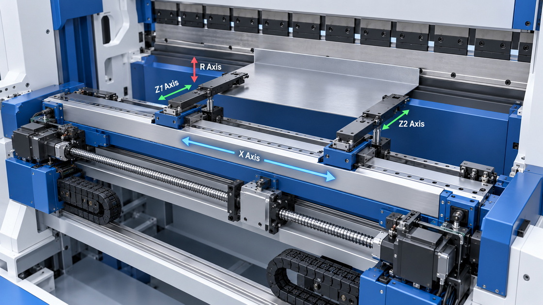
The number and type of back gauge axes should match the geometry of the parts you manufacture. More axes do not automatically make a press brake better. They make it more adaptable when your jobs involve different flange depths, asymmetric shapes, wide sheets, multiple gauging points, or complex bend sequences.
| Back Gauge Axis | Typical Movement | Primary Function | Best Application |
|---|---|---|---|
| X Axis | Forward and backward | Sets gauging depth and flange length | Essential for almost every press brake job |
| R Axis | Up and down | Adjusts stop-finger height | Different tooling heights, return flanges, complex profiles |
| Z1 Axis | Left and right | Positions the left gauge finger | Wide, narrow, asymmetric, or multi-point parts |
| Z2 Axis | Left and right | Positions the right gauge finger | Independent support and positioning of complex workpieces |
| X1 and X2 Axes | Independent forward and backward movement | Allows different gauging depths at two finger positions | Tapered, angled, irregular, or non-parallel parts |
The X-axis is the standard gauging axis. It sets the distance from the die centerline to the back gauge fingers and directly affects flange length. The R-axis moves the fingers vertically. It helps avoid interference and allows the machine to support different material thicknesses, tooling heights, and part geometries.
The Z1 and Z2 axes move fingers independently along the width of the machine. They are especially useful for long workpieces, narrow blanks, offset bends, and asymmetrical parts. In advanced systems, X1/X2 configurations give each finger independent depth movement for specialized profiles.
A standard CNC back gauge configuration is often described as X + R + Z1 + Z2. The right selection should be based on actual drawings and bend sequences, not simply the highest available axis count.
Back gauge faults rarely begin as complete machine failures. More often, they appear as small but repeatable production abnormalities. An experienced operator notices the pattern before the problem becomes expensive.
| Symptom | Likely Cause | First Check |
|---|---|---|
| Flange dimensions drift during a batch | Loose coupling, backlash, worn ball screw, encoder feedback issue, inadequate lubrication | Inspect drive components, guide rails, lubrication, and encoder cables |
| Left and right flange lengths do not match | Z-axis finger misalignment, gauge beam not parallel, loose finger assembly | Measure each finger from the lower die reference |
| CNC position is correct but finished flange is wrong | Incorrect offset, damaged finger, die reference error, setup error | Compare physical finger position with controller display |
| Back gauge moves slowly or makes unusual noise | Contamination, dry rails, bearing wear, damaged ball screw, misalignment | Clean, lubricate, and inspect mechanical motion components |
| Axis cannot home or loses zero | Encoder, limit switch, cable, drive, servo, or reference parameter issue | Inspect connections, alarms, and homing procedure |
| Operators constantly add manual program corrections | Lost calibration, mechanical play, historical offsets masking the defect | Verify calibration before adding more offsets |
| Gauge finger shifts after a collision | Bent finger, loose fasteners, damaged beam or rail alignment | Stop production and inspect mechanical alignment |
| Complex parts are hard to position consistently | Insufficient axis capability or unsuitable finger design | Evaluate X/R/Z-axis upgrade or custom retrofit |
The most important rule is this: do not treat every bad flange as an operator error. If the same variation repeats across shifts, programs, and operators, investigate the gauge system before changing programs again.
Back gauge motion relies on components such as ball screws, guide rails, bearings, servo motors, couplings, encoders, and electrical cables. Contamination on guide rails, inadequate lubrication, loose couplings, worn bearings, damaged encoder cables, and poor axis alignment can all create position error or unstable movement.
Before working behind a press brake, apply your company's lockout/tagout procedure, isolate energy sources, secure the work area, and follow the machine manufacturer's safety documentation. Calibration or mechanical adjustment should only be performed by trained personnel.
Start with evidence, not assumptions. Record:
- Programmed back gauge position
- Actual measured flange dimension
- Material type and thickness
- Tooling and V-die opening
- Which gauge finger was used
- Axis position shown on the CNC control
- Error direction and magnitude
- Whether the error changes across the bed
- Whether the error worsens during a production batch
A consistent 1.0 mm error may point to an offset or reference issue. An error that changes from part to part may indicate mechanical play, rail contamination, loose mounting, or encoder feedback instability.
A wrong flange dimension is not always a back gauge fault. Check whether the problem comes from:
- Incorrect material thickness
- Springback variation between material lots
- Wrong die opening
- Worn punch or V-die
- Incorrect bend deduction or bend allowance
- Sheet not seated fully against both fingers
- Material distortion before bending
- Burrs or damaged sheet edges preventing consistent contact
Use the same material, tooling, and bend method during diagnosis. Otherwise, you may confuse bending variation with positioning variation.
Metal chips, abrasive dust, oil residue, and foreign material can interfere with smooth motion and repeatable positioning. Clean the back gauge beam, linear rails, ball screw area, finger contact faces, and sensor surfaces according to the machine manufacturer's maintenance requirements.
Do not use a general-purpose lubricant without confirming compatibility. Incorrect lubrication can attract contamination or damage seals. Apply only the specified lubricant and interval for the machine's guide rails, ball screws, and moving assemblies.
With power isolated where required, inspect:
- Ball screw straightness and visible damage
- Coupling tightness between servo motor and ball screw
- Bearing condition at screw supports
- Finger mounting bolts and locking hardware
- Linear guide condition
- Back gauge beam straightness
- Signs of collision damage
- Loose cable carriers or cable strain
- Belt, rack, or pinion wear on lateral-axis systems
Mechanical play cannot be corrected permanently by entering more software offsets. If an axis shifts under load or changes position between cycles, repair the mechanical source before recalibration.
If an axis fails to home, moves to an unexpected position, or repeatedly loses reference, inspect encoder and limit-switch connections. Check cables for abrasion, oil contamination, loose terminals, or damage near cable carriers and moving sections.
Use the servo drive or CNC diagnostic functions where available. A qualified technician can compare commanded movement with actual encoder feedback, inspect alarm history, and verify that the axis returns to the same reference point repeatedly. Encoder-cable damage, poor connections, and improper homing references are common contributors to positioning faults.
Use traceable measurement equipment such as a calibrated digital caliper, gauge block, straightedge, or dial indicator. Measure the actual distance from each gauge finger to the lower die reference at several locations and compare it with the CNC display.
Check:
- Right-side finger position
- Left-side finger position
- Beam parallelism across its travel
- Finger height and squareness
- Repeatability after repeated moves to the same programmed location
If one finger is correct and the other is not, the issue may be local to the finger or Z-axis. If both fingers show the same consistent deviation, the X-axis reference or controller offset may be incorrect. If the error changes at different X positions, inspect backlash, ball screw condition, rail alignment, and encoder feedback.
A practical calibration check compares the physical stop position with the controller's displayed position at multiple points throughout the back gauge travel range.
After adjustments, run test bends using consistent scrap material. Measure the finished flange length with a verified measuring tool. Repeat the test at several back gauge positions and, for long machines, at multiple locations across the bed.
Document:
- Date and machine identification
- Technician or operator name
- Initial error
- Inspection findings
- Components adjusted or replaced
- Calibration values
- Test-bend measurements
- Final acceptance result
A calibration log turns troubleshooting into a repeatable maintenance process. It also helps identify recurring wear, collisions, temperature-related variation, or problem jobs before they become production failures.
A correct calibration aligns the CNC controller's commanded position with the physical location of the gauge fingers. Calibration is appropriate when the machine is mechanically sound but the displayed position and actual position no longer match.
Calibrate or verify calibration after:
- A tooling collision or material crash
- Machine relocation or major maintenance
- Ball screw, encoder, finger, rail, or servo replacement
- Control replacement or parameter restoration
- Repeated dimensional drift
- Extended production of tight-tolerance parts
- A noticeable left-to-right flange mismatch
- Any incident that may have moved or damaged the gauge assembly
A quick daily check using a known reference part can detect problems early. Higher-volume operations should establish a documented schedule for measured verification, backlash inspection, lubrication, and periodic full calibration. The exact interval should follow the press brake manufacturer's requirements, usage intensity, and quality-control needs.
1. Lock out the machine as required and remove material, tooling obstructions, and debris from the calibration area.
2. Inspect rails, ball screws, bearings, fingers, fasteners, and cables. Repair mechanical defects before making electronic corrections.
3. Home the back gauge axes following the machine-specific CNC procedure.
4. Place a traceable reference gauge or calibrated measuring device against the lower die reference.
5. Move the X-axis to a known programmed position and measure the actual distance to the gauge finger.
6. Repeat the measurement at the left and right fingers to verify beam and finger parallelism.
7. Compare actual readings with CNC display values and apply only authorized parameter corrections.
8. Move the gauge repeatedly to the same position to check repeatability.
9. Run test bends using controlled material and tooling, then measure the actual flange dimension.
10. Record final measurements and approve the machine only after it meets the required process tolerance.
CNDY-Press's calibration guidance recommends checking horizontal and vertical alignment, individual finger position, and test bends at different back gauge locations; it also recommends documenting measurements and adjustments for maintenance records.
Not every back gauge issue requires a new system. The correct option depends on the mechanical condition of the press brake, the age and capability of the control system, the part mix, and the cost of downtime.
| Situation | Best First Option | Why |
|---|---|---|
| Stable, consistent offset with no mechanical wear | Calibration | The controller reference may not match the physical finger position |
| Rough motion, noise, backlash, or position inconsistency | Mechanical repair and recalibration | Worn rails, ball screws, bearings, or couplings must be corrected first |
| Homing errors, alarms, or intermittent axis movement | Electrical/servo diagnosis | Encoder, cable, servo drive, limit switch, or parameter issue may exist |
| Machine is mechanically sound but uses obsolete manual stops | CNC back gauge retrofit | Modern servo positioning can improve setup speed and repeatability |
| Complex parts need independent fingers or more flexible positioning | Multi-axis retrofit | X, R, Z1, Z2, or X1/X2 capability may better support the application |
| Frame, hydraulics, electrics, and gauge are all worn | New press brake evaluation | A retrofit may not address the broader machine risk |
The key distinction is straightforward: calibration corrects a reference mismatch; repair corrects a physical defect; retrofit adds capability.
For example, a CNC back gauge that is consistently 0.8 mm too far from the die may need calibration. A gauge that varies between 0.3 mm and 1.5 mm from cycle to cycle likely needs mechanical or servo investigation. A manual back gauge that cannot support high-mix production may need a retrofit even if it still functions mechanically.
A press brake back gauge retrofit replaces or upgrades the positioning system while retaining the existing press brake frame and, where appropriate, the hydraulic system. A retrofit may include a new back gauge beam, servo motors, ball screws, linear guides, finger assemblies, CNC controller integration, electrical cabinet upgrades, safety interfaces, and commissioning.
A retrofit is often a strong option when:
- The press brake frame remains rigid and structurally sound
- Hydraulic performance is stable and economically maintainable
- The core limitation is slow, inaccurate, or manual part positioning
- The existing control is obsolete or difficult to support
- The factory needs X, R, Z1, and Z2 axis capability
- The machine has sufficient value to justify modernization
- Operators need shorter setup time and more repeatable production
- New-machine lead time or capital expenditure is restrictive
A retrofit may be a poor investment when the press brake also has major frame, ram, hydraulic, electrical, or safety deficiencies. In that situation, installing a modern back gauge may improve positioning but fail to solve the wider reliability and compliance risks.
For an accurate proposal, give your equipment supplier:
- Press brake brand, model, serial number, and production year
- Bed length, tonnage, throat depth, stroke, and daylight
- Existing CNC control and electrical configuration
- Current back gauge axis arrangement
- Main parts, drawings, and material thickness range
- Required flange tolerance
- Production quantity and shift schedule
- Desired X, R, Z1, Z2, or X1/X2 axes
- Existing tooling and clamping system
- Available electrical power and installation constraints
- Required safety upgrade scope
- Preferred OEM branding, interface language, and documentation needs
At CNDY-Press, we assess the machine as a complete operating system—not only as a back gauge. For suitable projects, we can provide customized CNC back gauge and press brake retrofit solutions for OEM and ODM customers, including servo-driven positioning, multi-axis configurations, control integration, commissioning, calibration, and application-based testing.
The lowest-cost way to maintain accuracy is to detect loss of repeatability early. A simple preventive-maintenance routine reduces the chance that a minor issue becomes scrap, downtime, or equipment damage.
- Wipe visible chips and debris from finger contact points and accessible rail areas
- Check for abnormal noise, vibration, or inconsistent axis motion
- Verify a known reference flange dimension before a tight-tolerance production run
- Inspect fingers for bending, looseness, burrs, or collision marks
- Confirm that material seats correctly against the stop faces
- Inspect lubrication condition according to the manufacturer's schedule
- Check fasteners, couplings, and finger assemblies for looseness
- Observe X-axis and Z-axis motion for hesitation or abnormal sound
- Review recurring operator offsets or repeated program edits
- Check cable routing for abrasion, crushing, or oil contamination
- Measure back gauge position against a traceable reference
- Check beam parallelism and left-right finger consistency
- Review calibration records and maintenance history
- Run a repeatability test at several programmed X positions
- Schedule service if errors increase or repeat inconsistently
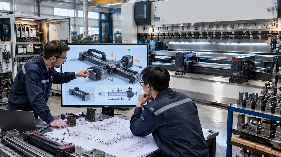
A press brake back gauge is not a secondary accessory. It is the positioning reference that turns a CNC bending program into a repeatable physical part. When dimensions drift, do not rely indefinitely on operator offsets and repeated trial bends. Identify the source: reference calibration, mechanical wear, encoder feedback, axis alignment, control limitations, or unsuitable gauge configuration.
For a sound press brake, disciplined inspection and calibration can restore dependable accuracy. For a machine limited by manual positioning, obsolete controls, or insufficient axis capability, a customized CNC back gauge retrofit can be a practical path toward faster setup and more consistent production.
Common causes include calibration loss, loose couplings, worn ball screws, damaged guide rails, bearing wear, collision damage, encoder problems, contaminated rails, improper lubrication, and finger misalignment. The correct diagnosis depends on whether the error is consistent, intermittent, or varies across the bed.
Verify positioning whenever you observe dimensional drift, after collisions, after mechanical repairs, after relocation, or when starting tight-tolerance work. The full calibration frequency should be based on machine usage, production tolerance, and the manufacturer's maintenance requirements. A reference-part check before critical production is a useful daily practice.
This often indicates that the gauge beam is not parallel to the die reference, one stop finger is misaligned, or a Z-axis finger is not positioned correctly. Measure both finger positions from the same lower-die reference and inspect the gauge beam, finger mounts, and lateral-axis operation.
A small, stable error may be corrected by an authorized calibration offset after physical measurement. However, offsets should not be used to hide mechanical backlash, damaged rails, loose couplings, encoder failure, or collision damage. Correct the mechanical or electrical cause first.
It can be, especially when the press brake frame and hydraulic system remain in good condition and the primary issue is obsolete positioning or control capability. If the machine also has major structural, hydraulic, electrical, or safety problems, a new press brake may provide better long-term value.
1. [CNDY-Press: What Your Press Brake Back Gauge Is Telling You]
2. [CNDY-Press: CNC Press Brake Back Gauge Calibration Guide]
3. [CNC Press Brake Back Gauge Guide: Axis Configurations and Calibration]
4. [Press Brake Back Gauge: Types, Axes, Calibration, and Troubleshooting]
5. [Troubleshooting Press Brake Servo System Malfunctions]


