


Views: 233 Author: CNDY-Press Publish Time: 2026-09-23 Origin: Site


Content Menu
● What Are Sheet Metal Bending Tolerances?
● Why Bending Tolerances Matter in OEM and ODM Manufacturing
● ISO 2768-1: A Starting Point for General Tolerances
>> When General Tolerances Are Not Enough
● Realistic CNC Press Brake Tolerances
● The Four Main Causes of Bending Variation
>> 1. Material Thickness and Mechanical Properties
>> 2. Press Brake Deflection and Machine Condition
>> 4. Setup, Handling, and Operator Process Control
● Air Bending vs. Bottom Bending vs. Coining
● How to Control Springback in CNC Press Brake Bending
● Design Rules for More Achievable Sheet Metal Tolerances
>> Keep Holes Away From Bend Lines
>> Identify Critical Dimensions Clearly
>> Plan for Tolerance Stack-Up
● Improving a Multi-Bend Electrical Enclosure
● Quality Control: How to Verify Bending Tolerances
>> Recommended Inspection Workflow
● Why Work With CNDY-Press for Custom Bending Projects?
● Get a Tolerance Review for Your Next Project
● FAQ
>> 1. What is a normal tolerance for sheet metal bending?
>> 2. Can a CNC press brake achieve ±0.1 mm accuracy?
>> 3. Why does stainless steel have more springback?
>> 4. Is air bending accurate enough for OEM production?
>> 5. How close can holes be placed to a bend line?
Sheet metal bending tolerances determine whether a fabricated part fits correctly, assembles efficiently, and performs as designed. For OEM and ODM projects, controlling sheet metal bending tolerances is not simply a press brake issue—it is a coordinated engineering task involving part design, material selection, CNC press brake capability, tooling, process validation, and quality inspection.
At CNDY-Press, we work with manufacturers, fabricators, and equipment integrators that need repeatable bending results across prototypes, custom-built machines, and production-scale sheet metal components. This guide explains how to specify achievable tolerances, manage springback, select a bending method, and build a more stable CNC press brake process.
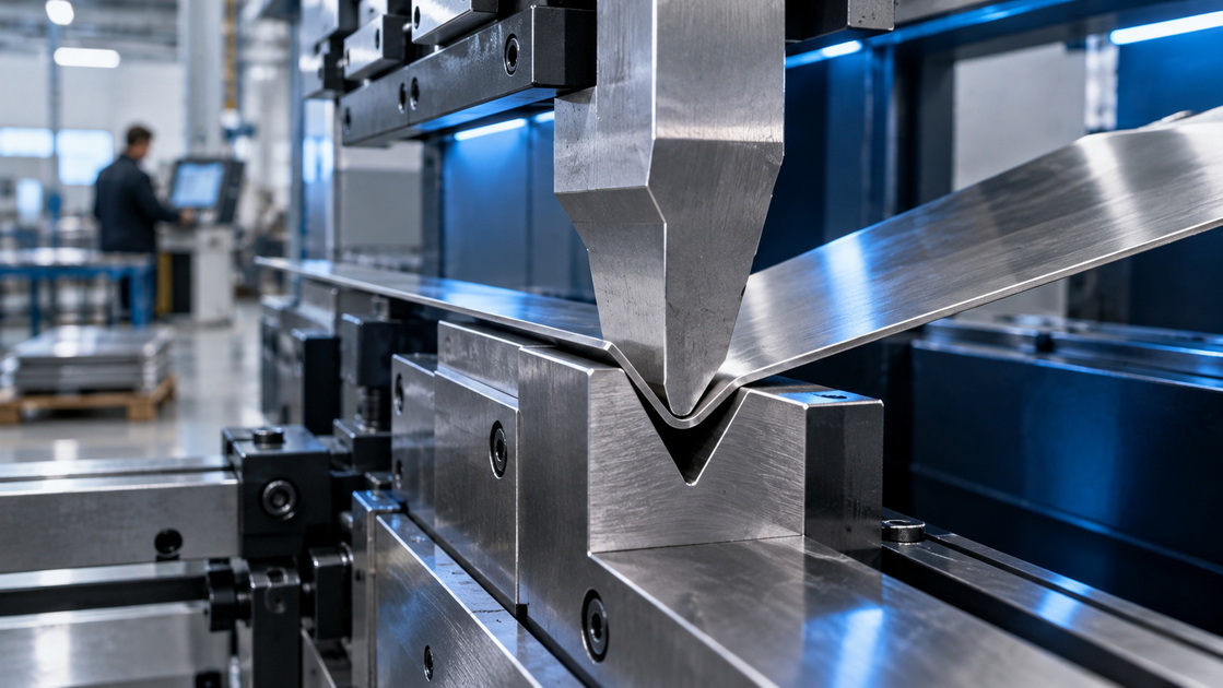
A sheet metal bending tolerance is the allowable difference between the design requirement shown on an engineering drawing and the actual dimension, angle, or geometry of the finished bent part.
In press brake fabrication, tolerance control includes more than the final bend angle. It can affect:
- Bend angle, such as 90° ± 0.5°
- Flange length or bend-to-edge distance
- Bend-line location
- Bend-to-hole position
- Part flatness and twist
- Bend-to-bend distance
- Assembly-critical dimensions
- Cosmetic quality, including scratches, marks, cracking, and distortion
A part may appear acceptable when measured at one bend, but still fail during assembly because several small deviations accumulate. This is particularly common in cabinets, electrical enclosures, machine guards, brackets, chassis, frames, and multi-bend welded assemblies.
For that reason, an experienced sheet metal manufacturer should evaluate tolerances as a complete system—not as isolated numbers on a drawing.
For OEM and ODM manufacturing projects, tolerance decisions influence product quality, delivery reliability, and total manufacturing cost.
If tolerances are too loose, parts may not align with mating components. Doors may not close correctly, fasteners may not line up, and assemblies may require manual adjustment. If tolerances are tighter than the functional design actually requires, production may become slower and more expensive.
The goal is not to specify the tightest possible tolerance. The goal is to specify the most economical tolerance that ensures functional performance.
| Design decision | Potential result |
|---|---|
| Tolerance is too loose | Poor fit-up, assembly problems, visible gaps, inconsistent product quality |
| Tolerance is unnecessarily tight | Higher scrap risk, slower production, more inspection, greater tooling and setup cost |
| Critical features identified early | Better process planning, clearer inspection, more stable production |
| General tolerances used appropriately | Simpler drawings and lower engineering administration |
| Material properties validated | More predictable springback and repeatable bending outcomes |
A practical engineering principle is simple: tighten only the dimensions that control function, fit, safety, or customer-facing appearance.
For dimensions that do not have individually stated tolerances, many engineering drawings use ISO 2768-1 as a general reference. ISO 2768-1 defines general tolerance classes for linear and angular dimensions, including fine, medium, coarse, and very coarse classes. It is intended to simplify drawings while establishing acceptable manufacturing limits for unspecified dimensions.
For example, a drawing may include a general tolerance note such as:
> ISO 2768-m
This typically indicates that unspecified dimensions should be manufactured according to the "medium" tolerance class of the applicable standard. However, engineers should not assume that a general tolerance note automatically solves every bending issue.
ISO 2768-1 is useful when:
- The part includes many non-critical dimensions
- The design needs a clear default tolerance framework
- The customer wants to avoid individually tolerancing every feature
- The component is a standard enclosure, bracket, cover, or structural sheet metal part
- The supplier and customer agree on the relevant tolerance class before production
Individual tolerances should be specified for:
- Mating interfaces
- Door and panel gaps
- Precision mounting locations
- Hole patterns that must align with other assemblies
- Sealing surfaces
- Hinges and latches
- Electrical or mechanical installation points
- Cosmetic features visible to end users
- Dimensions that control safety or regulatory compliance
A modern CNC press brake can produce highly consistent parts, but real-world capability depends on the machine, material, tooling, part geometry, setup method, and inspection system.
The following values are practical planning ranges—not universal guarantees. The actual tolerance should be confirmed through part review, sample bending, and first-article inspection.
| Feature | Typical production capability | Conditions that improve repeatability |
|---|---|---|
| Bend angle | ±0.5° to ±1.0° | Stable material, calibrated machine, appropriate tooling, angle correction |
| High-precision bend angle | Around ±0.25° to ±0.5° | Advanced CNC control, angle measurement, controlled material lots |
| Backgauge-controlled flange | ±0.1 mm to ±0.3 mm | Correct setup, rigid part support, stable gauge positioning |
| Bend-to-hole relationship | ±0.2 mm to ±0.5 mm | Proper hole-to-bend spacing and controlled blank accuracy |
| Multi-bend formed part | ±0.3 mm to ±0.8 mm or more | Optimized sequence, tolerance-stack analysis, controlled handling |
| Coined or highly controlled bend | Potentially tighter | Specialized tooling, higher tonnage, slower production, validation trials |
These ranges should be evaluated at the component level. A simple one-bend bracket is very different from a large stainless-steel cabinet with several return flanges, formed louvers, cutouts, and welded features.
Two sheets with the same nominal thickness may not bend exactly the same way. Material thickness, yield strength, tensile strength, grain direction, coating, and temper can all influence the final angle and flange dimension.
High-strength material generally produces more springback than softer material. Springback is the elastic recovery that occurs after the punch pressure is released. The press brake may intentionally overbend the material so that it relaxes to the target angle afterward.
This is why material traceability matters for demanding OEM projects. When a part has critical formed features, the manufacturing team should confirm:
- Material grade
- Actual thickness
- Temper or condition
- Rolling direction
- Material certificate availability
- Batch consistency
- Surface finish or coating condition
Even a high-quality CNC press brake can produce inconsistent results if its mechanical condition is not maintained.
Important machine-control factors include:
- Ram parallelism
- Backgauge repeatability
- Hydraulic or servo stability
- Crowning or deflection compensation
- Tool clamping accuracy
- CNC program accuracy
- Angle correction data
- Routine calibration and preventive maintenance
Long bends are especially sensitive to deflection. Without compensation, a long part may bend more in the center or at the ends, creating inconsistent angles across the bend line.
Tooling affects both the bend angle and the inside bend radius. A worn punch, damaged die shoulder, poor alignment, or incorrect V-die opening can add variation before the operator even begins process adjustment.
For air bending, the V-die opening must be selected according to material thickness, material type, target bend radius, required tonnage, and surface-quality expectations.
A common practical guideline is to begin with a V-die opening approximately 8 to 12 times the material thickness for many standard applications. However, this is only a starting point. Harder materials, larger bend radii, special finishes, and thick plate applications may require a different tooling strategy.
CNC automation improves repeatability, but successful bending still depends on disciplined setup and process execution.
Key controls include:
- Correct material orientation
- Accurate backgauge setup
- Consistent reference edges
- Stable part support for large sheets
- Repeatable bend sequence
- Clear setup sheets
- First-article approval
- Defined in-process inspection intervals
- Fast response to material-batch changes
An experienced operator often recognizes process variation before it creates significant scrap. For example, a small angle shift on the first few parts may indicate a springback change, tooling issue, material variation, or incorrect program compensation.
The selected bending method has a major effect on achievable tolerance, setup flexibility, tooling cost, and cycle time.
| Bending method | How it works | Typical advantages | Main limitations | Best use case |
|---|---|---|---|---|
| Air bending | Punch forces sheet into a V-die without fully bottoming | Flexible, lower tonnage, faster setup, multiple angles with one die | More sensitive to springback and material variation | General fabrication and mixed production |
| Bottom bending | Material is pressed more closely into the die geometry | Better angular consistency than air bending | Higher force and more angle-specific tooling | More critical bends and repeat production |
| Coining | Very high force plastically forms the material into the tool shape | Maximum springback reduction and high precision potential | High tonnage, tooling cost, slower cycle time | Aerospace, medical, precision mechanisms |
Air bending remains the most common approach because it offers flexibility and lower tooling requirements. However, it requires reliable springback compensation. Coining can significantly reduce springback, but it requires much higher force; industry guidance commonly notes that coining can require several times the force of air bending.
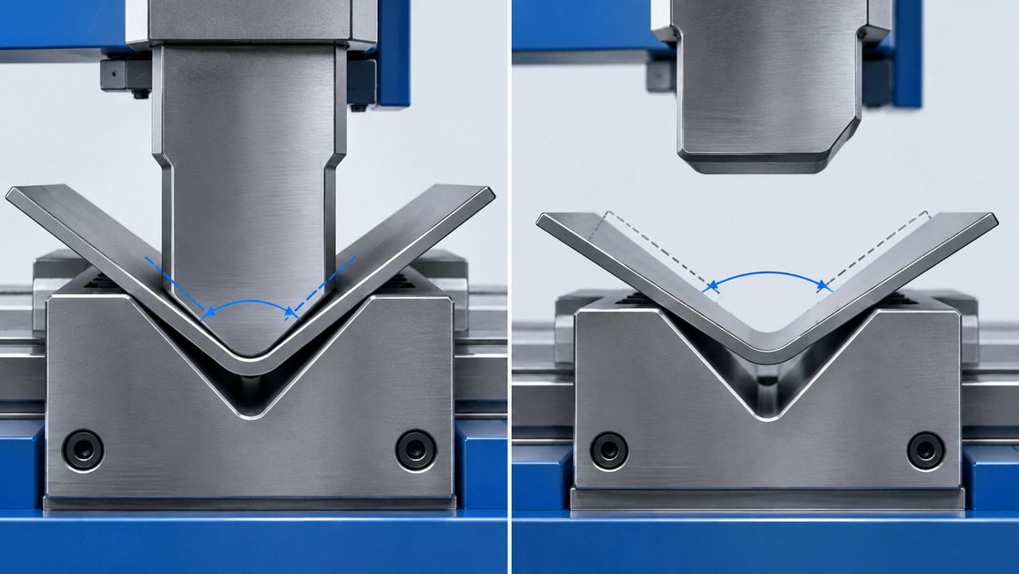
Springback cannot be ignored. It must be predicted, measured, and compensated for.
A reliable springback-control process includes the following steps:
1. Confirm the material specification before production, including grade, actual thickness, and temper where applicable.
2. Choose the correct punch and die combination based on the material, desired inside radius, and required bend geometry.
3. Program an initial compensation angle based on historical process data, bending tables, simulation software, or controlled trial bends.
4. Run a first-article part using the actual production material—not only a different sample sheet.
5. Measure the finished angle after elastic recovery, not only while the part is under load.
6. Adjust the CNC program or angle compensation until the part meets the approved target.
7. Document the approved setup for repeat orders, including tooling, material, bend sequence, angle correction, and inspection method.
8. Monitor production samples to identify drift caused by tooling wear, machine changes, or material-lot variation.
Good tolerance control begins during product design. A part that is difficult to bend accurately may still be manufacturable, but it will require more setup time, more inspection, and a higher production cost.
Where possible, use a consistent inside bend radius throughout the same part. This simplifies tooling selection, CNC programming, and process control.
Holes positioned too close to a bend can become distorted or shift during forming. A practical minimum distance often starts at approximately twice the material thickness from the bend line, but the correct clearance depends on the hole size, bend radius, material, tooling, and functional requirement.
For precision projects, ask the manufacturer to review the drawing before final release.
Do not apply tight tolerances to every feature. Instead, identify the dimensions that truly matter for function.
Examples include:
- Distance between mounting holes
- Final enclosure width
- Hinge alignment
- Door gap
- Bracket interface location
- Sealing flange position
- Alignment between bent tabs and slots
A multi-bend part can accumulate variation. If three or four bends each have small dimensional variation, the final overall dimension may deviate more than expected.
For critical assemblies, engineers should perform a tolerance stack-up analysis before production. This evaluates how variation from individual bends, cut features, material thickness, and assembly references may combine in the final product.
Consider a fabricated electrical enclosure with four 90-degree bends, mounting holes, a removable door, and a gasket sealing flange.
A weak drawing may specify:
- All dimensions ±0.1 mm
- All angles ±0.25°
- No general tolerance standard
- No identification of assembly-critical features
- No material condition or grain-direction requirement
This approach may look precise, but it creates unnecessary manufacturing difficulty and cost.
A better engineering approach would be:
- Apply a suitable general tolerance note for non-critical dimensions.
- Individually tolerance mounting-hole locations, door opening dimensions, and gasket-contact features.
- Specify the material grade, thickness, surface condition, and coating requirements.
- Define the critical door gap and flatness requirements.
- Request first-article inspection for the initial batch.
- Confirm the inspection datum system and measurement method.
- Review the bend sequence with the fabrication partner before production.
The result is usually a part that is easier to manufacture, faster to inspect, and more likely to assemble correctly on the first production run.
A robust quality-control plan should match the risk level of the part.
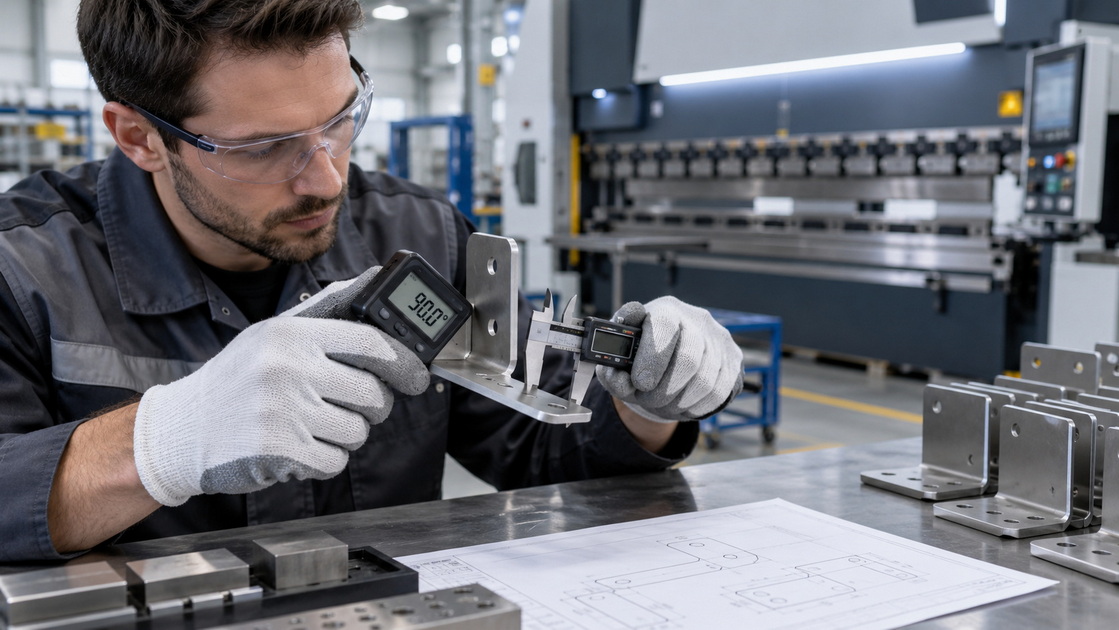
For non-critical parts, a calibrated tape measure, caliper, steel rule, height gauge, and digital angle finder may be sufficient. For complex or high-value assemblies, manufacturers may use coordinate measuring machines, laser scanning, dedicated fixtures, or optical systems.
Measurement uncertainty also matters. NIST defines measurement uncertainty as a parameter associated with a measurement result that characterizes the dispersion of values reasonably attributable to the quantity being measured. In practical terms, the inspection method must be capable of distinguishing meaningful part variation from measurement variation.
- Review drawings and identify critical-to-quality dimensions.
- Verify material before production.
- Inspect the first article before full production begins.
- Measure bend angles, flange lengths, overall dimensions, and critical hole locations.
- Record approved tooling, machine program, and inspection results.
- Perform in-process sampling at defined intervals.
- Use statistical process control for repeat production or high-volume programs.
- Investigate trends before they become out-of-tolerance production defects.

For custom sheet metal equipment and OEM/ODM manufacturing, the right supplier should contribute more than machine capacity. The supplier should help convert design intent into a stable and inspectable production process.
CNDY-Press supports CNC press brake and sheet metal processing projects with a focus on:
- Customized CNC press brake solutions
- OEM and ODM manufacturing support
- Sheet metal processing equipment integration
- Application-based machine configuration
- Engineering communication before production
- Tooling, process, and tolerance consultation
- After-sales service and technical support
Whether you are developing a new machine enclosure, industrial cabinet, structural bracket, electrical housing, or customized metal product, early tolerance review can reduce rework, shorten sampling cycles, and improve production consistency.
If your project includes critical angles, complex multi-bend parts, stainless steel components, thick plate, or assembly-sensitive enclosures, do not wait until production to discover tolerance problems.
For many standard production parts, a bend-angle tolerance of approximately ±0.5° to ±1.0° and a backgauge-controlled flange tolerance of approximately ±0.1 mm to ±0.3 mm can be practical. Actual capability depends on material, thickness, tooling, machine condition, bend method, part size, and inspection method.
A CNC press brake may achieve approximately ±0.1 mm on certain controlled flange dimensions under suitable conditions. However, this should not be assumed for every part. Long parts, multi-bend assemblies, soft or thin material, variable material lots, and complex geometries can require wider tolerances.
Stainless steel often has higher strength and stronger work-hardening behavior than mild steel. After bending force is released, more elastic recovery can occur, causing greater springback. Tooling selection, overbending, and controlled first-article trials are important for stainless-steel bending.
Yes, air bending is widely used in OEM production because it is flexible and efficient. It can produce consistent results when the material, tooling, machine settings, springback compensation, and inspection process are well controlled. For unusually tight angles, bottom bending or coining may be more appropriate.
The required distance depends on material thickness, hole size, bend radius, tooling, and tolerance requirements. A common preliminary guideline is to keep holes at least about two times the material thickness away from the bend line, but critical projects should be reviewed by the fabrication engineer.
1. [ISO 2768-1 General Tolerances for Linear and Angular Dimensions — ZEISS Quality Forum] — Reference tables and descriptions for ISO 2768-1 tolerance classes, including general linear and angular tolerances. [qualityforum.zeiss]
2. [SIST ISO 2768-1:1999 — General Tolerances for Linear and Angular Dimensions] — Scope and intended use of ISO 2768-1 for linear and angular dimensions without individual tolerance indications. [standards.iteh]
3. [Springback Factor on the Press Brake — The Fabricator] — Explanation of overbending and elastic recovery in press brake forming. [thefabricator]
4. [Mastering Springback: A Guide to Sheet Metal Bending Precision — VICLA] — Discussion of the relationship between material strength, thickness, bend radius, and springback. [vicla]
5. [Measurement Uncertainty — National Institute of Standards and Technology] — Definition and metrology context for measurement uncertainty in inspection and quality systems. [nist]
6. [Original Article Reviewed: Master Sheet Metal Bending Tolerances: Engineering Guide — CNHAWE] — Source article reviewed for restructuring, expansion, technical-context improvement, and SEO enhancement. [cnhawe]


