


Views: 275 Author: CNDY-Press Publish Time: 2026-11-10 Origin: Site


Content Menu
● CNC Press Brake with 4 Axes vs 6 Axes at a Glance
● What Do Press Brake Axes Actually Control?
>> Z1 and Z2: Lateral Finger Position
● Machine Axes vs Backgauge Axes
● When a 4-Axis CNC Press Brake Is a Practical Choice
● When a 6-Axis CNC Press Brake Adds Value
>> Complex Parts Still Need a Feasibility Check
● Does a 6-Axis Press Brake Produce Better Accuracy?
● Compare the Complete Job, Not One Axis Speed
>> Where Six Axes May Save Time
>> Where the Difference May Be Small
● A Practical Investment Model
● Controller and Software Requirements
● Tooling, Tonnage, and Working Envelope Still Come First
● How to Compare Four and Six Axes in a Factory Trial
>> Step 1: Choose a Mixed Part Set
>> Step 2: Record All Manual Interventions
>> Step 3: Measure Complete Job Time
>> Step 4: Inspect Consecutive Parts
>> Step 5: Repeat a Stored Job
● Maintenance, Training, and Future Upgrades
● Choosing a Configuration with CNDY-Press
>> 1. Is a 6-Axis CNC Press Brake Always Better?
>> 2. Can a Common 6-Axis Machine Gauge Tapered Parts Independently?
>> 3. Does CNC Crowning Count as an Axis?
>> 4. Will Six Axes Reduce Operator Skill Requirements?
>> 5. Can Four Axes Be Upgraded Later?
A CNC press brake with 4 axes typically controls Y1, Y2, X, and R. A common 6-axis configuration adds Z1 and Z2, allowing programmed lateral positioning of the backgauge fingers. The main benefit is greater setup flexibility—not automatically higher bending accuracy, more tonnage, or faster ram movement.
However, manufacturers do not always count axes the same way. A "6-axis press brake" and a "6-axis backgauge" can describe substantially different machines.
For fabricators and machinery distributors, the purchasing priority should be configuration: which physical movements are included, how they support your parts, and whether they justify the additional investment.
At CNDY-Press, our stated business includes CNC press brakes, sheet-metal processing equipment, and OEM/ODM manufacturing. From an equipment-selection perspective, the most useful comparison begins with representative drawings and production requirements—not the axis number on a quotation.
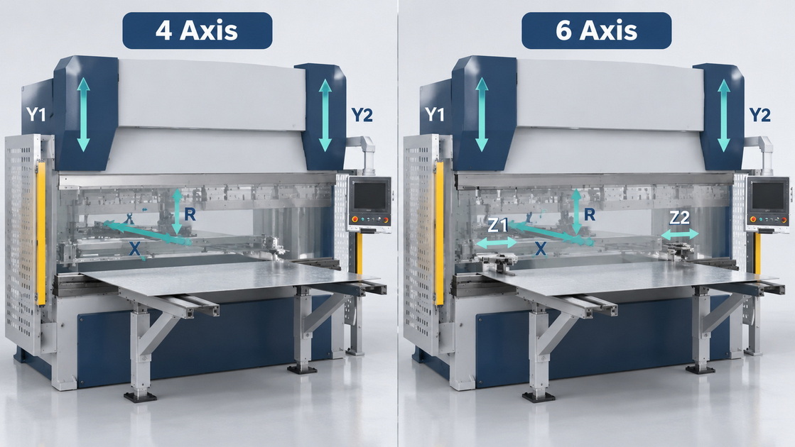
This article compares a common hydraulic configuration: four machine axes versus six machine axes.
| Comparison Point | Typical 4-Axis CNC Press Brake | Typical 6-Axis CNC Press Brake |
|---|---|---|
| Controlled axes | Y1, Y2, X, R | Y1, Y2, X, R, Z1, Z2 |
| Ram control | Independently controlled ram sides | Same basic arrangement |
| Backgauge depth | Programmed X movement | Programmed X movement |
| Backgauge height | Programmed R movement | Programmed R movement |
| Finger spacing | Commonly adjusted manually | Programmed lateral adjustment |
| Main advantage | Simpler configuration for suitable work | More flexible finger positioning |
| Typical opportunity | Repeated parts with stable gauging needs | Varied widths and multiple gauging locations |
| Main limitation | More manual finger repositioning | Additional cost and integration requirements |
| Accuracy implication | Depends on the complete machine and process | Additional axes do not inherently improve every bend |
Always obtain the axis list in writing. Supplier terminology can differ.
On a synchronized hydraulic press brake, Y1 and Y2 typically control the two sides of the ram.
Their feedback and control system help maintain the required ram position and synchronization.
They do not eliminate variations caused by material thickness, tensile strength, tooling condition, or springback.
The X axis moves the backgauge toward or away from the bending line.
Its position helps establish the flange dimension when the workpiece is correctly seated against the gauge fingers.
Accurate X positioning is valuable, but finished dimensions also depend on the blank, bend allowance, tooling, and operator handling.
The R axis adjusts backgauge height.
This allows the fingers to contact an appropriate area as the part changes shape through successive bends.
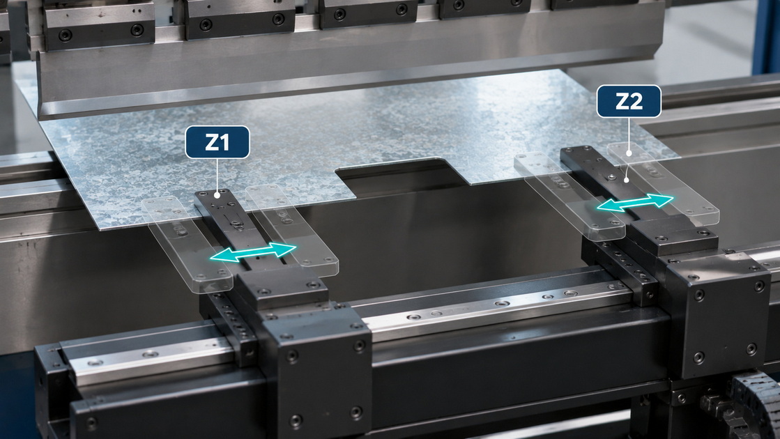
Z1 and Z2 move the gauge fingers along the machine's working length.
Programmed lateral positioning can place each finger near a suitable reference area, move it around a cutout, or align it with a different tooling station.
These movements do not provide independent front-to-back positioning. That requires additional or differently configured axes.
A six-axis machine may contain two ram axes and four backgauge axes.
By contrast, a six-axis backgauge may control:
- X1 and X2: independent depth.
- R1 and R2: independent height.
- Z1 and Z2: independent lateral position.
Adding Y1 and Y2 produces eight controlled machine movements before crowning or other functions are considered.
This distinction matters for tapered parts and nonparallel reference edges.
A machine with Y1, Y2, X, R, Z1, and Z2 cannot independently position its two fingers at different depths merely because it has six axes.
Suppliers often use "4+1" or "6+1" to describe a configuration with CNC crowning.
Crowning compensates for deflection along the bending length. It is not another backgauge positioning direction.
Request a clear description of the crowning mechanism, adjustment method, and controller integration rather than relying on the label.
A four-axis machine can be well matched to production where finger positions remain suitable across many bends.
Examples include straightforward brackets, channels, panels, and other components with accessible parallel reference edges.
It may be appropriate when:
- Part widths fall within a relatively stable range.
- Operators rarely change finger spacing.
- Bends use a consistent tooling station.
- Batch sizes are large enough to absorb manual setup.
- The budget is better allocated to tooling, handling, or training.
A four-axis configuration should not be dismissed as inherently low precision. With suitable construction, calibration, tooling, and process control, it can produce demanding work.
Its economic limitation emerges when manual adjustments repeatedly interrupt production.
A six-axis machine becomes more attractive when lateral finger positions change frequently.
Programmed Z1/Z2 movement can help with:
- Components of different widths.
- Parts containing notches or cutouts.
- Several tooling stations along the bed.
- Bend sequences requiring different contact locations.
- Repeat orders that benefit from stored finger positions.
The benefit comes from reducing avoidable setup work and making positioning more consistent.
More axes cannot overcome every geometry problem.
A deep box may require different tooling clearance. A narrow flange may need an alternative gauging strategy. A heavy panel may require support equipment.
The correct question is not simply whether the part is complex. It is whether programmed lateral finger movement resolves a specific production constraint.
Not automatically.
Both configurations may use comparable ram control, backgauge components, and crowning systems.
Additional lateral axes can improve the repeatability of finger placement and reduce manual setup variation. However, they do not directly correct:
- Incorrect material data.
- Inconsistent blank dimensions.
- Tool wear.
- Poor machine alignment.
- Variable springback.
- Inadequate crowning settings.
- Incorrect workpiece seating.
Distinguish axis positioning specifications from finished-part tolerances.
A published backgauge repeatability figure does not establish the achievable flange dimension or bend angle for every application.
A faster backgauge movement does not necessarily produce a faster completed part.
Total job time includes programming, tooling setup, finger positioning, part handling, bending, inspection, and corrective work.
The additional movements may reduce manual intervention between bends or repeat jobs.
This can be valuable in high-mix production, where setup tasks occur frequently.
If both fingers remain in the same lateral positions for an entire batch, Z1/Z2 may provide limited ongoing cycle-time benefit.
For large or awkward components, handling may dominate the process. Suitable supports or lifting assistance could offer greater value than additional backgauge axes.
Do not assume every movement can occur simultaneously. Safe sequencing, travel limits, and collision avoidance influence actual cycle time.
Use your own production observations rather than an unsupported percentage-saving claim.
Estimate:
Annual labor-time value=Minutes saved per relevant setup×Relevant setups per year×Loaded hourly labor cost/60
Then consider additional measurable effects:
- Reduced setup-related scrap.
- More consistent repeat-job preparation.
- Changes in programming time.
- Additional maintenance and service costs.
- Financing and software costs.
Do not automatically count all saved minutes as extra sales. Additional output has commercial value only when demand and the rest of the production system can support it.
A simple payback estimate can inform the decision, but it is not a guaranteed return.
The controller must support the installed movements and integrate them correctly.
Graphical programming, bend-sequence calculation, and collision detection can assist setup. Their effectiveness depends on accurate machine, tooling, finger, and part data.
Before purchase, confirm:
1. The enabled axis configuration.
2. Included software functions and licenses.
3. Offline programming availability.
4. Tool-library creation and maintenance.
5. Backgauge collision modeling.
6. Program backup and transfer procedures.
7. Training for the supplied configuration.
A capable controller does not prove that every optional function is installed.
Simulation also does not replace safeguarding or a controlled first-piece procedure.
Axis count does not increase rated force, bending length, daylight, stroke, throat depth, or tool loading capacity.
Evaluate these fundamentals separately.
| Requirement | Why It Matters |
|---|---|
| Tonnage and load distribution | Determines whether the bend is within machine and tooling limits |
| Punch and die geometry | Influences radius, flange feasibility, and clearance |
| Daylight and stroke | Affects tool installation and part removal |
| Backgauge travel | Determines reachable reference positions |
| Finger geometry | Affects contact, clearance, and usable gauging range |
| Crowning | Helps manage deflection along longer bends |
| Workpiece support | Influences handling and consistent seating |
Six axes cannot compensate for an unsuitable punch-and-die combination or an inaccessible reference edge.
A quotation may list generous X, R, and Z travel while the required part remains difficult to gauge.
Usable positioning depends on finger shape, extension, nearby tooling, minimum finger separation, and collision restrictions.
Ask the supplier to demonstrate the actual contact points on your part—not simply move the backgauge through its advertised travel.
Also check repeat-job recovery. A saved program is only useful when the correct tooling, finger arrangement, material assumptions, and machine references are restored.
Use the same representative parts and define the trial before the demonstration.
Include a repeat bracket, a multi-bend component, and a part with difficult gauging locations.
Count finger adjustments, tooling changes, program edits, regripping, and corrective bends.
Separate first-piece setup from steady production.
Measure agreed dimensions and angles across an application-appropriate run. Do not accept only selected demonstration pieces.
Check whether the operator can restore production without undocumented adjustments.
This test reveals whether extra axes solve your actual bottleneck.
Additional axes introduce more drives, motors, sensors, cables, and calibration requirements.
That does not inherently make a machine unreliable, but it increases the importance of documentation and service access.
Request:
- Electrical drawings and drive identification.
- Backup copies of machine parameters.
- Lubrication and inspection instructions.
- Recovery procedures after interrupted movement.
- Spare-parts availability.
- Operator and maintenance training.
If starting with four axes, do not assume a six-axis upgrade will be straightforward. Mechanical provisions, drives, wiring, controller capability, software, and integration may all need modification.
CNDY-Press undertakes CNC press-brake and OEM/ODM projects according to the supplied company background.
A useful inquiry should include drawings, material grades, thicknesses, batch sizes, required tolerances, and planned tooling.
For distributors, also define branding, documentation, spare parts, training, and service responsibilities.
No. It is better suited to work that benefits from programmed lateral finger positioning. Stable, repetitive production may not justify the additional investment.
Not necessarily. Independent finger depth requires X1/X2 or an equivalent mechanism. Z1/Z2 alone changes lateral position, not depth.
Supplier conventions differ. Crowning is often shown as "+1," but buyers should verify the physical function rather than compare totals alone.
They can reduce certain manual adjustments, but operators still need tooling knowledge, safe handling skills, and an understanding of material behavior.
Sometimes, but only with confirmed mechanical, electrical, controller, and software compatibility. Obtain an upgrade scope and quotation before relying on that option.
1. Selmach Machinery. ["Press Brake Axes Explained: Choosing the Movements Your Work Actually Needs."] Explains Y1/Y2, X, R, Z1/Z2, common four- and six-axis packages, manual lateral positioning, and the distinction between machine-axis and backgauge-axis counts. [selmach]
2. SC Machinery. ["What Is Press Brake Axis?"] December 18, 2024. Describes typical 4+1, 6+1, and 8+1 configurations and identifies crowning separately. Supplier terminology is not treated as a universal naming standard. [shen-chong]
3. LVD Group. ["Easy-Form Series" brochure.] Manufacturer documentation distinguishing basic backgauges from independent X1/R1/Z1 and X2/R2/Z2 arrangements, including applications involving nonparallel flanges. [lvdgroup]
4. Delem. ["DA-66T" product brochure, hosted by Axe & Status.] Describes graphical programming, bend-sequence calculation, collision detection, crowning control, machine setup, and optional X1/X2 programming. Actual availability depends on the supplied machine configuration. [axestatus]
5. Delem. ["DA-66T Reference Manual," hosted by ManualsLib.] Technical background on gauge-position calculation, safe movement sequencing, machine geometry, tooling data, and collision-related constraints. [manualslib]
6. ACCURL. [Published multiaxis press-brake and backgauge configuration.] Illustrates the distinction between four-axis X/R/Z1/Z2 backgauges and six-axis X1/X2/R1/R2/Z1/Z2 backgauges. Model-specific performance claims are not generalized here. [accurl]
7. CNDY-Press. ["About Us."] Company background for CNC press brakes, sheet-metal equipment, OEM/ODM, customization, training, and service. No independent factory audit or comparative machine test was conducted. [cndypress]


