


Views: 233 Author: CNDY-Press Publish Time: 2026-10-30 Origin: Site


Content Menu
>> Bend Allowance Does Not Directly Prevent Cracking
● Bend Allowance vs Bend Deduction vs K-Factor
● Bend Allowance Formula and Angle Convention
>> Do Not Confuse Bend Angle With Included Angle
● Bend Allowance Chart for 90° Bends
● Calculate the Flat Length of a Bracket
>> Step 1: Calculate Bend Allowance
>> Step 2: Calculate Outside Setback
>> Step 3: Calculate Bend Deduction
>> Step 4: Calculate Flat Length
● Why a Generic Chart May Not Match Your Press Brake
>> The Actual Radius May Differ From the CAD Radius
>> Material Name Is Not a Complete Specification
>> Springback and Flat Development Are Different Issues
● How to Build a Shop-Specific Bend Allowance Chart
>> 1. Prepare and Measure a Test Blank
>> 2. Produce the Intended Finished Angle
>> 3. Determine the Effective Bend Deduction
>> 4. Calculate an Effective K-Factor Where Appropriate
● Correcting the Same Error Twice
● How Sensitive Is Bend Allowance to K-Factor?
● What to Include in a Controlled Bend Library
● How CNDY-Press Can Support Process Development
● FAQ
>> 1. Does increasing K-factor increase bend allowance?
>> 2. Can I use K = 0.33 for every material?
>> 3. Why does my CAD flat pattern differ from the shop's result?
>> 4. Should we store bend allowance or bend deduction?
>> 5. Will a more advanced press brake eliminate bend allowance errors?
A bend allowance chart helps translate a finished sheet-metal design into the correct flat blank. However, a chart is useful only when its assumptions match the material, bend angle, inside radius, and forming process.
For CNC press brake buyers and fabricators, the challenge is not finding a table online. It is developing validated bending data that engineering, programming, production, and inspection can use consistently.
My approach is to treat generic charts as calculation references—not production guarantees. Start with clearly defined geometry, test the actual material and tooling, and retain the results in a controlled bend library.
This guide explains bend allowance, bend deduction, and K-factor, provides a transparent calculation chart, and shows how to calibrate the data using a physical test piece.
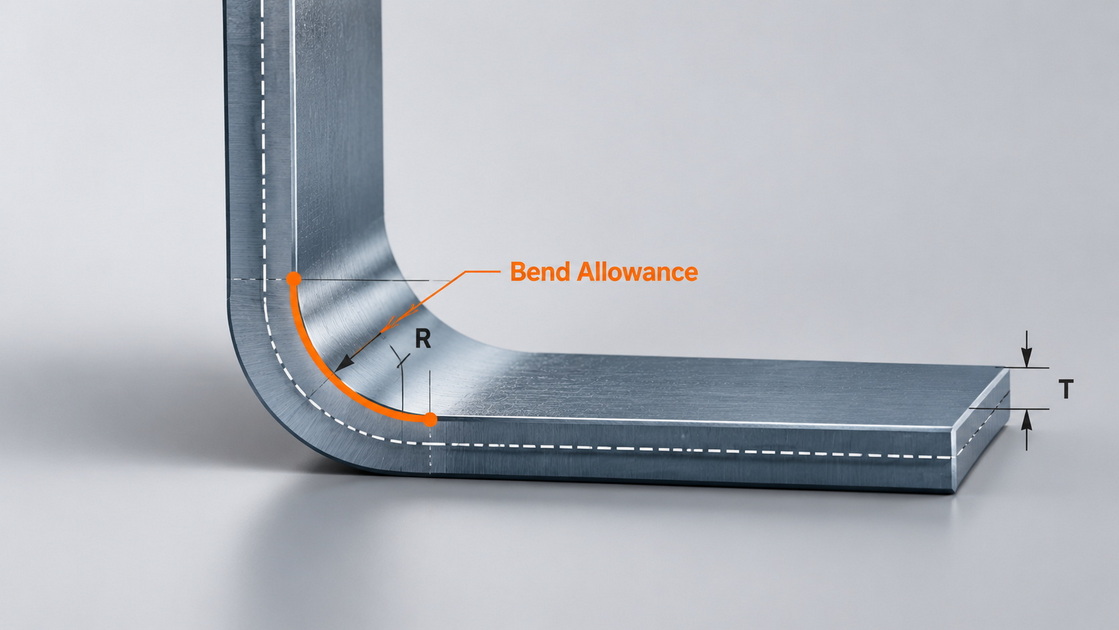
Bend allowance, usually abbreviated BA, is the developed arc length of the bend measured along the material's neutral axis.
During bending, material on the outside stretches while material on the inside compresses. The neutral axis is the idealized layer between them where longitudinal length remains unchanged.
A flat pattern can therefore be calculated as:
Lflat=Lstraight 1+BA+Lstraight 2
Here, the straight lengths stop at the bend tangent points. They are not the outside flange dimensions measured to the virtual sharp intersection.
That distinction is essential. Adding bend allowance to the wrong dimensions produces an incorrect blank.
Correct bend allowance supports dimensional development. It does not, by itself, prevent cracking, wrinkling, or incorrect bend angles.
Those problems require separate evaluation of material condition, radius, grain orientation, tooling, support, and process settings.
A correctly sized blank can still be bent incorrectly.
| Term | Meaning | How it is used |
|---|---|---|
| Bend allowance | Neutral-axis arc length through the bend | Added to tangent-to-edge straight lengths |
| Bend deduction | Difference between the summed outside flange dimensions and flat length | Subtracted from outside dimensions |
| K-factor | Neutral-axis distance from the inside surface divided by thickness | Used to calculate bend allowance |
| Outside setback | Distance from the virtual outside intersection to the tangent point | Connects outside dimensions with bend geometry |
These are related methods, not interchangeable labels.
K=d/T
Where:
- d is the neutral-axis distance from the inside surface.
- T is material thickness.
K-factor is dimensionless. It is not a length, a springback angle, or a fixed property assigned solely by material name.
For a fixed radius, thickness, and bend angle, increasing K increases calculated bend allowance. It correspondingly reduces bend deduction.
That relationship follows directly from the formula.
For a bend angle expressed in degrees:
BA=πA/180×(R+KT)
Where:
- A is the change in direction from the flat condition.
- R is the finished inside bend radius.
- T is material thickness.
- K is the selected K-factor.
Use consistent length units throughout.
A flat sheet has a bend angle of 0°. A right-angle bend has a bend angle of 90°.
If a drawing gives an internal included angle of 120°, the corresponding bend angle is 60° for this convention.
At 90°, the distinction is easy to miss because both values are identical. At other angles, it can create a substantial calculation error.
Confirm the convention used by your CAD system, controller, and calculator.
The following chart is calculated from the stated inputs. It is not an experimentally verified material chart.
All rows assume:
- A 90° bend angle.
- The listed finished inside radius.
- The listed illustrative K-factor.
- Dimensions in millimeters.
| Thickness | Inside radius | Assumed K | Bend allowance | Outside setback | Bend deduction |
|---|---|---|---|---|---|
| 1.0 | 1.0 | 0.33 | 2.089 | 2.000 | 1.911 |
| 1.5 | 1.5 | 0.33 | 3.134 | 3.000 | 2.866 |
| 2.0 | 2.0 | 0.33 | 4.178 | 4.000 | 3.822 |
| 2.0 | 2.0 | 0.40 | 4.398 | 4.000 | 3.602 |
| 3.0 | 3.0 | 0.40 | 6.597 | 6.000 | 5.403 |
| 4.0 | 4.0 | 0.40 | 8.796 | 8.000 | 7.204 |
The two 2 mm rows demonstrate why thickness and radius alone do not fully define a bend allowance chart.
Do not interpret either K-factor as universally correct for mild steel, stainless steel, or aluminum.
Consider a simple bracket with:
- Thickness: 2.0 mm.
- Inside radius: 2.0 mm.
- Bend angle: 90°.
- Assumed K-factor: 0.40.
- Outside flange dimensions: 50 mm and 50 mm, measured to the virtual sharp.
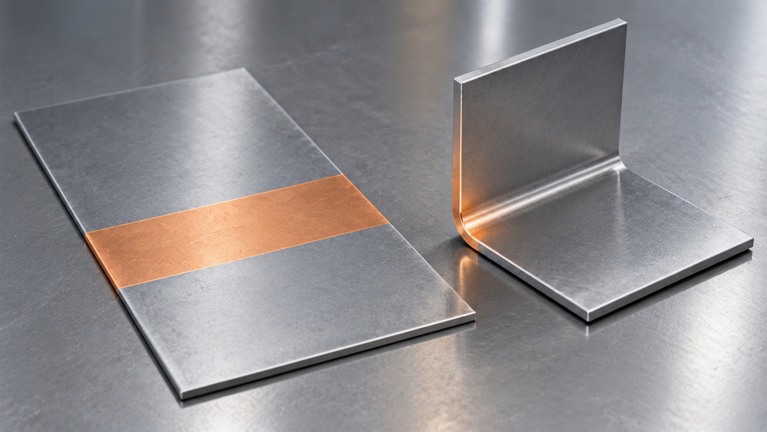
BA=π/2×(2+0.40×2)
BA=4.398 mm
For a conventional single bend:
OSSB=(R+T)×tan(A/2)
Therefore:
OSSB=(2+2)×tan45∘=4.000 mm
BD=2OSSB−BA
BD=8.000−4.398=3.602 mm
Lflat=50+50−3.602
Lflat=96.398 mm
The alternative allowance method gives the same result:
Lflat=(50−4)+(50−4)+4.398
The agreement is a useful check that the dimension references are consistent.
In air bending, the achieved radius depends on material and tooling conditions. It should not automatically be assumed equal to the punch-tip radius.
For mild steel, published industry guidance discusses a naturally formed radius around 15%–17% of the die opening under relevant air-bending conditions.
That is an estimating rule—not a universal relationship for every alloy, tool, or forming method.
"Aluminum" does not identify alloy, temper, thickness variation, or bendability.
Likewise, different steel grades and material conditions can behave differently.
A useful bend library records the actual material specification and forming setup rather than assigning one permanent K-factor to an entire material family.
Springback affects the released geometry. It is commonly addressed through the bending process and suitable compensation.
Changing K-factor to hide an angle problem can corrupt the flat-pattern data.
First stabilize the finished angle and geometry. Then evaluate whether the blank development matches the required dimensions.
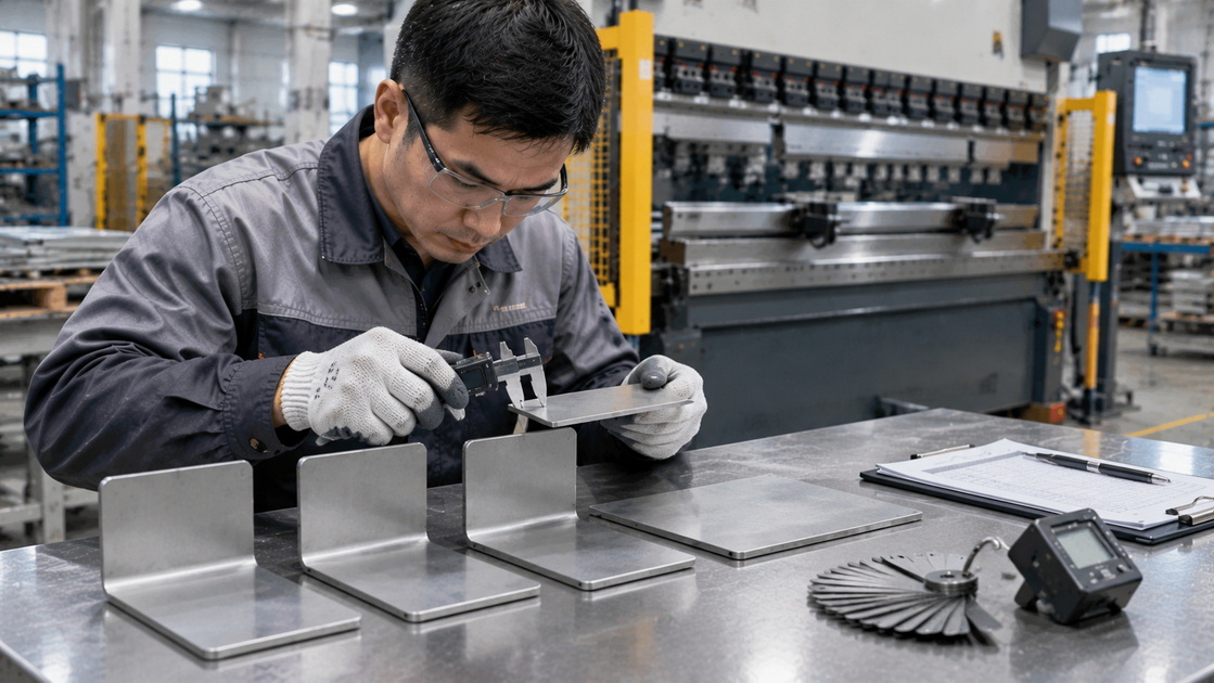
Use the production material and intended tooling.
Record:
- Actual blank length.
- Measured thickness.
- Material grade and condition.
- Rolling direction relative to the bend line.
- Punch and die identification.
- Die opening.
- Forming method.
Choose a simple coupon with sufficient flange length for reliable support and measurement.
Measure the released angle after bending.
If the angle is incorrect, establish a stable process before interpreting dimensional differences as a bend-development error.
For a simple single-bend coupon using consistent outside virtual-sharp dimensions:
BD=L1+L2−Lblank
For example, if the blank is 100.0 mm and the two outside dimensions are 50.0 mm and 53.6 mm:
BD=3.6 mm
These are illustrative measurements, not reported production results.
If the finished angle is 90°, thickness is 2.0 mm, and the measured inside radius is 2.0 mm:
BA=2(2+2)−3.6=4.4 mm
Rearranging the allowance formula:
With θ=π/2, the effective K-factor is approximately 0.401.
Radius uncertainty affects the inferred K-factor. If radius measurement is unreliable, retaining a validated bend deduction for that specific setup may be more practical than claiming a precisely identified K.
Measure multiple coupons, then verify a representative production component.
One coupon provides a starting observation, not evidence of long-term process capability.
A common workflow risk arises when engineering changes the flat pattern while production independently changes a bend correction for the same dimensional complaint.
The next batch may then contain both adjustments.
Prevent this with a controlled correction process:
1. Identify whether the issue concerns angle, flange position, overall development, or measurement.
2. Assign responsibility for the correction.
3. Record the approved change.
4. regenerate or update affected files.
5. Verify the next component before releasing the batch.
Do not change K-factor simply because one flange is short. A gauging or datum error can produce a different problem from incorrect overall blank development.
With angle, radius, and thickness held constant:
ΔBA=θTΔK
For a 90° bend in 2 mm sheet, changing K by 0.05 changes calculated allowance by approximately 0.157 mm per bend.
Several similarly affected bends can create a meaningful developed-length difference.
This calculation illustrates sensitivity. It does not predict every finished flange error, because the part's datums, gauging, geometry, and tolerances also influence the result.
| Category | Recommended fields |
|---|---|
| Material | Grade, condition, thickness, supplier information where relevant |
| Geometry | Finished angle, radius, dimension convention |
| Tooling | Punch, die, opening, tool position |
| Process | Machine, forming method, relevant settings |
| Development | BA, BD, or K method and approved value |
| Validation | Sample quantity, measurements, inspection method |
| Control | Revision, approval date, applicable limits |
Revalidate when material, tooling, method, or other relevant process conditions change.
Avoid extrapolating one successful 90° test to hems, joggles, unusual radii, or different forming methods without additional checks.
CNDY-Press manufactures sheet-metal processing equipment and offers OEM, ODM, and customer-specific production services.
When evaluating a CNC press brake, provide representative drawings, material specifications, tolerances, and your current flat-pattern method.
Request a trial that records tooling, finished geometry, program corrections, and inspection results. This creates a clearer basis for machine acceptance than a demonstration of one visually satisfactory bend.
For customized equipment projects, also define who owns the approved bend data and how it will transfer into the buyer's programming workflow.
A bend allowance chart is a useful calculation tool, but production approval should rely on measured results under defined conditions.
Keep bend allowance separate from bend deduction, state the angle convention, and validate the radius and development method.
Yes. With angle, radius, and thickness unchanged, a higher K increases calculated bend allowance and reduces bend deduction.
No. It can be an illustrative starting assumption, but it requires validation for the material, geometry, tooling, and forming method.
Check dimension references, angle convention, radius, material thickness, bend method, and development settings. Also verify that angle and gauging problems are not being mistaken for flat-pattern errors.
Either can work with consistent definitions. Bend deduction is convenient for outside dimensions; allowance works with tangent-based straight lengths. Use the method your workflow supports clearly.
No. Better control may improve repeatability, but incorrect development assumptions still produce incorrectly sized blanks.
1. [PrimaPress — Bend Allowance Chart: Complete Guide]. Original article reviewed for restructuring. Its unsupported chart values, reversed K-factor explanation, and conflation of development with defect prevention were not carried forward. No user comments were visible in the retrieved content or supplied separately. [prima-press]
2. [SOLIDWORKS — Bend Allowance and Bend Deduction]. Primary documentation on flat-length methods and virtual-sharp measurement references. [help.solidworks]
3. [SOLIDWORKS — Understanding Bend Allowance Options]. Explanation of K-factor, neutral-line development, and allowance-versus-deduction workflows. [blogs.solidworks]
4. [Javelin Technologies — What Are Bend Allowance, Bend Deduction and K-Factor?]. Supporting definitions and the relationship \(BD=2OSSB-BA\). [javelin-tech]
5. [The Fabricator — How an Air Bend Turns Sharp]. Application-specific discussion of naturally formed air-bend radii and tooling considerations. [thefabricator]
6. [CNDY-Press — About Us]. Company equipment scope and stated OEM, ODM, and customized manufacturing services. [cndypress]


