


Views: 266 Author: CNDY-Press Publish Time: 2026-10-19 Origin: Site


Content Menu
● Why Press Brake Tooling Selection Requires a System Approach
● Choose the Bending Method Before the Tool Profile
● How to Select the V-Die Opening
>> Use the Rule of Eight as a Starting Point
>> Do Not Apply One Ratio to Every Material
● Inside Bend Radius and Minimum Flange Length
>> The Punch Radius Does Not Always Determine the Finished Radius
>> A Half-V Flange Rule Can Be Misleading
● Selecting Punch Profiles for Real Part Geometry
>> Acute, Radius, Offset, and Hemming Tools
● Check Units and the Entire Load Path
>> Do Not Confuse kN With Metric Tonnes-Force
>> Check Every Load-Bearing Component
● Short Tools Can Be Overloaded on Large Machines
● Tooling Compatibility: Verify Drawings, Not Just Style Names
● Tool Steel, Hardness, and Surface Finish
>> Harder Does Not Automatically Mean Stronger
>> Control Marking Without Ignoring Capacity
● Collision Checks and Safe Setup Are Part of Tool Selection
● A Six-Step Tooling Approval Workflow
>> 2. Confirm Machine Interfaces
>> 5. Run Representative Trials
>> 6. Freeze the Approved Setup
● Specifying a CNDY-Press OEM or ODM Project
>> 1. Is a V-Opening of Eight Times Thickness Always Correct?
>> 2. Can a Higher-Tonnage Machine Safely Use Any Tool?
>> 3. Why Does the Finished Radius Differ From the Punch Radius?
>> 4. Can I Mix Tools From Different Manufacturers?
>> 5. Should Worn Tooling Be Sharpened In-House?
Press brake tooling selection starts with the part drawing, material properties, and bending method—not simply the press brake's maximum tonnage. The correct punch and die combination must produce the required geometry while remaining within the limits of the tooling, holders, adapters, and machine.
For fabricators, equipment distributors, and OEM buyers, the objective is repeatability: producing acceptable parts without excessive adjustment, premature tool damage, or unsafe loading.
CNDY-Press develops and manufactures CNC press brakes and related sheet-metal processing equipment, with OEM, ODM, and customized production services. This guide provides a practical framework for specifying tooling as part of a complete bending system.
It also addresses important gaps in the supplied article, including force-unit consistency, short-flange limitations, concentrated loading, and the risks of treating tooling styles as a simple quality hierarchy. No separate customer comments were supplied, so no testimonials are invented.
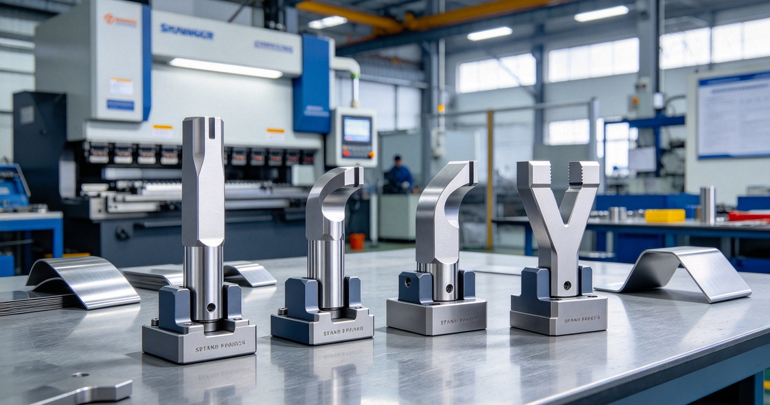
The punch and die contact the workpiece, but their performance depends on the surrounding equipment.
A suitable tool can still produce poor results when it is installed in an incompatible holder, programmed with incorrect dimensions, or used with unsuitable material assumptions.
Before selecting CNC press brake tooling, establish:
- Material grade and condition.
- Actual thickness range.
- Tensile-strength range.
- Bend length and required angle.
- Inside-radius requirements.
- Minimum flange dimensions.
- Surface-finish acceptance criteria.
- Machine and clamping-system details.
My recommendation is to resolve these inputs before requesting a tooling quotation. Otherwise, suppliers may recommend different products because they are solving different interpretations of the job.
Air bending, bottoming, and coining impose different contact conditions and force requirements.
| Method | Basic principle | Main selection consideration |
|---|---|---|
| Air bending | Sheet contacts the punch and die shoulders without fully conforming to the die | Die opening, penetration, material variation, and springback |
| Bottoming | Tool geometry constrains the material more closely near the final angle | Matched geometry, thickness control, and higher loading |
| Coining | High pressure creates substantial localized plastic deformation | Explicitly rated tooling and machine capability |
Do not apply an air-bending force chart to a bottoming or coining operation.
Likewise, avoid using a universal multiplier to approve a higher-force process. Obtain application-specific guidance from the machine and tooling suppliers.
The discussion below primarily concerns conventional V-die air bending unless stated otherwise.
For many mild-steel air-bending applications, a V-opening around eight times the material thickness provides a useful initial reference.
For 2 mm material, that suggests evaluating a 16 mm opening.
This is not an approval rule. The selected opening must also accommodate the required radius, flange length, material behavior, and available capacity.
A narrower opening generally increases required bending force. A wider opening generally produces a larger natural inside radius and requires more flange support.
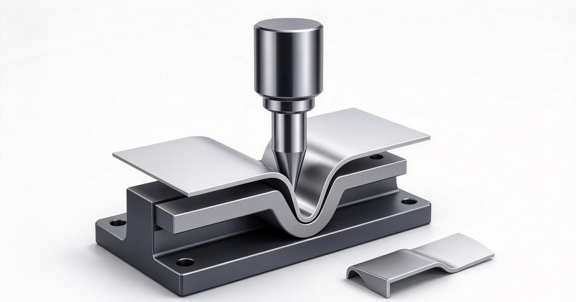
Stainless steel, aluminum, high-strength steel, and different tempers can behave differently.
Review material-supplier recommendations, particularly where cracking or limited ductility is a concern. Grain direction, cut-edge condition, and the specified radius may affect the result.
If the drawing demands a radius that conflicts with the material's bendability, changing the die alone may not solve the problem.
In conventional air bending, the natural inside radius depends strongly on the V-opening and material behavior.
Bystronic gives approximately 16% of the V-opening as a mild-steel reference. A 16 mm opening therefore suggests an approximate 2.6 mm natural inside radius.
That is an estimate, not a guaranteed result.
Punch-tip radius still matters. An unsuitable tip can create excessive local pressure or an unwanted crease. It should not be selected independently of the material and die.
The supplied article suggests minimum-flange guidance around half the V-opening. That is too simplified for approving production tooling.
Bystronic gives approximately 77% of the V-opening as a reference for conventional bending in its guide. Acute prebends for hemming can require longer flanges.
Use the selected tooling manufacturer's chart and confirm how the flange dimension is defined.
A proposed short flange must remain supported through the bend. If it does not, consider specialized tooling or a design change rather than simply increasing force.
A standard punch can cover many uncomplicated bends.
Select its angle, radius, working height, and load rating for the application. "Standard" does not establish one universal geometry or capacity.
Gooseneck profiles provide clearance around previously formed flanges.
However, the recess changes the tool's cross-section. Verify the exact profile's rating rather than assuming the same capacity as a straight punch.
Specialized tools can simplify difficult parts:
- Acute tools support tighter included angles and appropriate prebending.
- Radius tools support specified larger-radius applications.
- Offset tools can form closely spaced bends.
- Hemming systems combine or sequence prebending and flattening.
Each requires application-specific capacity and clearance checks. A tool that forms the first bend successfully may still trap the part during a later operation.
The supplied article labels a force formula as producing metric tons while describing a conversion from newtons to kilonewtons.
That creates a consequential unit inconsistency.
Kilonewtons measure force. A metric tonne is mass; a metric tonne-force is approximately 9.81 kN. Some catalogs use "tons" as shorthand, so the convention must be confirmed.
Use a manufacturer-approved chart or validated calculation with clearly defined units, material strength, geometry, and bending method.
Do not copy an unlabeled online formula into a machine program.
Review the permissible loading of:
1. Punch.
2. Die.
3. Upper holder.
4. Lower holder and crowning assembly.
5. Adapters or risers.
6. Press brake structure and permitted loading position.
The machine's overall tonnage does not override a lower tooling or holder limit.
For short or off-center bends, obtain the machine manufacturer's applicable loading restrictions.
A common purchasing mistake is comparing total bending force only with total machine capacity.
Tool ratings are frequently expressed as load per unit length.
WILA illustrates that a 100 mm segment rated at 1,000 kN/m can sustain 100 kN when the load is evenly distributed.
That does not authorize the same total force through a much shorter contact area.
For segmented or staged setups, identify which sections actually carry load during each operation. Do not distribute force mathematically across unused tools simply because they are installed nearby.
Also avoid assuming that a single force reading resolves every local-stress concern. Consult the supplier for unusual contact conditions.
American, European, and New Standard descriptions are useful categories, but they are not complete compatibility specifications.
The supplied article presents these styles as a simple progression from lower to higher quality. That is not a reliable purchasing framework.
Precision, retention, alignment, and changeover features can exist across different systems.
Confirm:
- Tang profile and dimensions.
- Load-bearing surfaces.
- Retention mechanism.
- Holder engagement.
- Working height.
- Die base interface.
- Adapter requirements.
- Permitted load.
A nominal tang width alone does not establish safe interchangeability.
Tooling selection should consider steel grade, heat treatment, toughness, working-zone hardness, geometry, and manufacturing quality together.
A surface-hardness figure does not establish total load capacity.
Nor should one hardness value be assumed to apply throughout a tool. Some products use localized hardening to combine wear resistance with other required properties.
Request the supplier's specification rather than treating every "60 HRC" claim as equivalent.
Polished, coated, and prepainted materials may require additional surface protection.
Options include appropriate die-shoulder geometry, protective media, or specialized supported dies.
Such measures can change friction, dimensions, or forming behavior. Validate the complete setup.
Remove debris and inspect contact surfaces before diagnosing every mark as a material problem.
Check the full bending sequence, including formed flanges, backgauge fingers, clamps, ram, supports, and part removal.
Simulation is valuable only when its tool and machine geometry match the physical setup.
Safety-device settings must also suit the actual machine and operation. A generic statement that any beam interruption always causes immediate stopping and retraction is not an adequate safeguarding specification.
Use the machine's instructions, applicable requirements, and a task-specific assessment. Never bypass a safeguard to accommodate unsuitable tooling.
Setup, adjustment, and maintenance must follow the prescribed energy-control and support procedures.
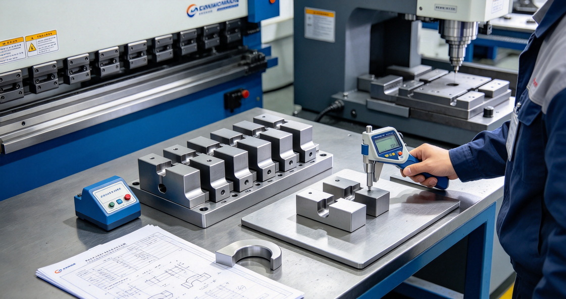
Group parts by material, thickness, geometry, finish, and production volume.
A coherent tooling library can reduce unnecessary changeovers.
Provide holder drawings, working heights, stroke, daylight, and loading limits.
Evaluate V-opening, radius, flange support, punch clearance, and bend sequence together.
Check force units, loaded length, component ratings, and loading position.
Use representative production material. Inspect angle, radius, flange dimensions, surface condition, and repeatability.
Record tool identities, dimensions, material assumptions, program revision, and inspection results.
Changes to material or tooling should trigger review rather than automatic reuse of the old settings.
For a customized CNC press brake proposal, send CNDY-Press representative drawings, material specifications, thickness ranges, bend lengths, tolerances, and production targets.
Include existing tooling details if compatibility is required.
Ask the team to identify the proposed clamping system, tooling package, capacity assumptions, clearance review, and acceptance tests.
The company background supplied for this article establishes equipment manufacturing and customization services. It does not independently establish particular tooling brands, certifications, or guaranteed tolerances.
Reliable press brake tooling selection connects part geometry, material behavior, capacity, compatibility, and safe operation.
Start with the drawing. Check the V-opening and flange support. Verify the complete load path. Then validate the setup with representative material.
No. It is a useful mild-steel air-bending starting point. Radius, flange length, material properties, tooling limits, and the selected process can require another solution.
No. The punch, die, holders, adapters, and permitted machine loading can impose lower limits. Check load per unit length and actual contact conditions.
In air bending, material behavior and die opening influence the natural radius. The sheet does not necessarily conform to the punch nose.
Only after verifying interfaces, working heights, tolerances, retention, and load ratings. Similar appearance or a shared style description is insufficient.
Do not casually grind or sharpen precision profiles. Reworking can change height, radius, hardness, and alignment. Use manufacturer-approved assessment and refurbishment procedures.
1. [CNHAWE — "The Ultimate Guide to Press Brake Tooling Selection," August 4, 2025]. Supplied source article. Reviewed for coverage and reconstructed with corrections to force-unit handling, flange guidance, compatibility assumptions, and safety wording. [cnhawe]
2. [Paul LeTang, Bystronic — "The Rules of Press Brake Tool Selection," May 2019]. Manufacturer guidance on V-opening selection, natural radius, minimum flange length, tool profiles, clearance, and surface protection. [bystronic]
3. [WILA — "Learn About WILA Tools and Load Capacity"]. Source for load-per-length interpretation, the 100 mm segment example, evenly distributed loading, and holder limitations. [wilatooling]
4. [WILA — "Tool Tang"]. Explains tooling identification through tang shape and dimensions. [wilatooling]
5. [AMADA — Euro Press Brake Tooling Catalog]. Manufacturer charts connecting thickness, radius, V-opening, force, and minimum bendable flange. Confirm applicability to the tooling supplied. [amada]
6. [WILA — Press Brake Tooling]. Product-specific explanation of hardened compression and wear zones. [wilatooling]
7. [U.S. Occupational Safety and Health Administration — Powered Press Brakes]. Official overview of point-of-operation hazards and safeguarding approaches. [osha]


