


Views: 243 Author: CNDY-Press Publish Time: 2026-09-05 Origin: Site


Content Menu
● Why Add a Press Brake Robot?
● Start with Application Engineering, Not Equipment Selection
>> Define the Production Target
● Choose the Right Robotic Bending Cell Configuration
>> Core Components of a Robotic Press Brake Cell
● Prepare the Facility Before Delivery
>> Facility Readiness Checklist
● Make Safety Engineering a Design Requirement
● Program for Stable Production, Not Just a Demonstration
>> Programming and Validation Steps
● Train Operators for New Responsibilities
● Monitor OEE, Quality, and Changeover Performance
● Partner with CNDY-Press for a Customized Robotic Bending Solution
● FAQ
>> 1. What types of parts are best for a press brake robot?
>> 2. Can an existing CNC press brake be retrofitted with a robot?
>> 3. How much space does a robotic bending cell need?
>> 4. Does robotic press brake automation improve bending quality?
>> 5. Is a press brake robot safe to operate?
Adding a press brake robot can turn a manual bending department into a more consistent, traceable, and scalable production operation—but only when the cell is specified around real parts, real changeovers, and real safety requirements. For sheet-metal manufacturers, OEMs, and fabricators, the most successful robotic bending cell projects begin with application engineering rather than with a robot quotation.
At CNDY-Press, we view a CNC press brake robot as a complete manufacturing system: press brake, robot, tooling, end-of-arm tooling, safety equipment, programming, material flow, quality control, and operator training. This guide explains how to plan, install, validate, and continuously improve a robotic press brake solution for high-volume, repeatable, or labor-intensive sheet-metal bending work.
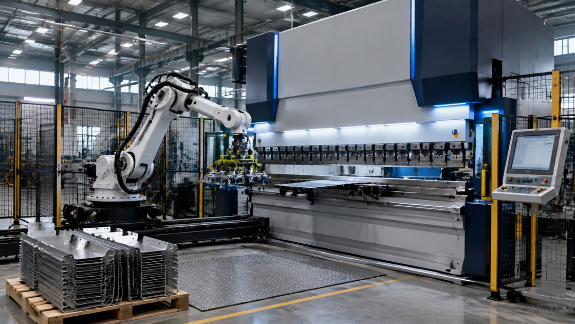
A robotic press brake bending cell automates repetitive loading, positioning, bending, unloading, and stacking tasks that would otherwise depend heavily on manual handling. The objective is not simply to replace an operator. The objective is to create a stable bending process that can maintain output, accuracy, and safety across shifts.
For the right application, press brake automation can help manufacturers address several common operational challenges:
- Skilled press brake operator shortages.
- Inconsistent handling of large, heavy, or awkward parts.
- Long manual cycle times on recurring parts.
- Production bottlenecks between laser cutting and welding.
- Quality variation caused by inconsistent part positioning.
- Limited unattended or lights-out production capacity.
- Safety exposure during repetitive material handling.
Robotic bending is especially suitable for manufacturers that produce repeat orders, families of similar parts, cabinet components, electrical enclosures, brackets, elevator parts, appliance panels, HVAC components, furniture frames, and other formed sheet-metal products.
However, automation is not automatically the best answer for every part. A highly complex component with frequent design changes, a very small batch, unstable blank quality, or difficult manual tool changes may require a different solution. A professional feasibility review should happen before the equipment configuration is finalized.
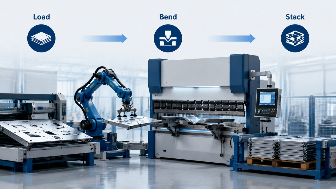
The first question should not be, "Which robot should we buy?" It should be, "Which parts should the robot bend, and what must the complete cell achieve?"
A press brake robot must be designed around the workpiece. That includes material type, thickness, blank dimensions, bend sequence, flange geometry, weight, surface sensitivity, tolerances, batch size, and required output.
Before selecting an automated bending cell, collect production data for representative parts. Ideally, analyze at least three groups:
1. High-runner parts with stable and repeatable demand.
2. Labor-intensive parts that are difficult, heavy, or ergonomically challenging to handle manually.
3. Part families that share tooling, material types, bend directions, or gripper requirements.
The following table can help a production team assess whether a part is a strong candidate for a press brake robot.
| Evaluation factor | Strong automation candidate | Potential challenge |
|---|---|---|
| Annual volume | Repeatable medium- or high-volume demand | One-off or rarely repeated parts |
| Part geometry | Stable, predictable bend sequence | Severe interference or highly variable geometry |
| Material condition | Consistent blank size and flatness | Variable blanks, burrs, warpage, or inconsistent film |
| Part handling | Heavy, repetitive, or awkward manual handling | Extremely flexible or easily deformed workpieces |
| Tooling | Standard or repeatable tooling setup | Frequent manual tool changes |
| Quality requirement | Tight repeatability and traceability needs | Tolerances beyond the capability of the upstream process |
| Changeover | Similar jobs grouped into batches | Very high mix with unpredictable scheduling |
Expert insight: A robotic cell does not correct poor upstream processes. If laser-cut blanks vary in size, hole locations, burrs, flatness, or material thickness, the robot may expose those problems more quickly than a manual operator would. Reliable automation starts with stable incoming parts.
A clear target makes the project easier to engineer and measure. Avoid broad statements such as "we need more automation." Instead, define measurable objectives.
Examples include:
- Increase bending output for a specific product family.
- Reduce manual handling of parts above a defined weight.
- Run selected jobs during breaks, weekends, or an additional shift.
- Improve first-pass yield on a repetitive bending operation.
- Reduce setup time through offline programming and standardized tooling.
- Create traceable production data for OEM customer requirements.
A useful baseline includes:
- Current cycle time per part.
- Average setup and changeover time.
- Rework and scrap rate.
- Operator attendance requirement.
- Machine utilization.
- Labor hours per batch.
- Annual part volume.
- Quality rejection reasons.
A robotic press brake system should be configured as a coordinated cell, not as a press brake with a robot placed beside it. The final solution may include a CNC press brake, industrial robot or collaborative robot, loading table, blank-detection system, grippers, part-turning device, tool-storage solution, safety enclosure, automatic stacking area, and production-monitoring software.
A typical automated bending cell includes the following elements:
- CNC press brake: Selected by tonnage, bending length, open height, throat depth, ram speed, crowning system, backgauge configuration, and controller capability.
- Industrial robot: Sized according to payload, reach, cycle-time requirements, workpiece geometry, and required robot motion.
- End-of-arm tooling: Vacuum grippers, magnetic grippers, mechanical grippers, combination grippers, or customized tooling designed for specific surfaces and part shapes.
- Tooling system: Punches, dies, clamps, adapters, and—in some applications—automatic tool changing.
- Safety system: Perimeter fencing, interlocked doors, laser scanners, light curtains, safety PLCs, emergency stops, and defined access zones.
- Material handling: Loading stations, conveyors, blank separators, stacking systems, pallets, and interfaces with upstream laser cutting or storage systems.
- Programming software: Offline simulation, collision checking, bend sequencing, robot-path generation, and production reporting.
For high-throughput applications, a larger industrial robot and integrated material flow may be appropriate. For lower-volume production, a compact robotic or collaborative solution may offer a more practical entry point. The right choice depends on the part mix—not on whether a cell looks more advanced on paper.
The financial case for a press brake robot should include more than labor savings. A narrow calculation based only on one operator's hourly wage can underestimate both the benefits and the implementation work required.
A better model considers total production impact.
- Equipment purchase and installation cost.
- Robot, gripper, tooling, safety equipment, and software.
- Site preparation, electrical work, compressed air, and network integration.
- Training and initial programming.
- Labor redeployment or avoided recruitment costs.
- Increased machine utilization.
- Reduced manual handling and ergonomic exposure.
- Lower scrap, rework, and quality variation.
- Potential additional-shift or unattended production.
- Maintenance, spare parts, and annual service requirements.
Industry sources report that robotic bending applications can improve consistency, enable extended operating hours, and reduce repetitive heavy-lifting exposure. At the same time, published ROI figures vary widely because part geometry, batch size, labor cost, utilization, and integration scope vary widely from plant to plant. A current market overview notes that fully integrated robotic bending cells may range from approximately $200,000 for simpler cobot-assisted arrangements to $600,000 or more for advanced systems with functions such as automatic tool changing, vision guidance, and AGV connectivity. These figures should be treated only as a preliminary planning reference—not as a project quotation.
Use the following framework during feasibility planning:
Annual Benefit=Labor Impact+Additional Contribution Margin+Scrap/Rework Reduction+Avoided Hiring Cost+Safety and Ergonomic Value−Annual Operating Cost
Then calculate:
Payback Period=Total Project Investment/Annual Benefit
For example, if a robotic bending cell allows a manufacturer to run a stable part family beyond normal staffed hours, reduces repetitive handling, and improves first-pass quality, its value may come from a combination of labor redeployment, higher output, and reduced quality loss—not from labor reduction alone.
Important: Do not base the investment case on theoretical maximum cycle time. Use validated simulation, sample-part trials, realistic loading and unloading times, expected changeovers, and planned downtime.
A robotic press brake installation often requires more preparation than a standalone machine. Delays frequently occur when floor loading, electrical supply, compressed air, network access, safety zoning, or material flow are considered too late.
Before installation, confirm the following items:
- Adequate floor space for the machine, robot reach, fencing, loading, unloading, maintenance access, and material staging.
- Verified floor bearing capacity and levelness.
- Correct electrical voltage, capacity, grounding, and distribution.
- Stable compressed-air supply where pneumatic equipment is used.
- Lighting suitable for safe setup, inspection, and maintenance.
- Network connection for machine monitoring, remote support, or MES/ERP integration.
- Forklift or crane access for delivery and placement.
- Defined pathways for raw materials, finished parts, scrap, and operator access.
- Space for tooling storage and part-specific fixtures.
- A clear plan for machine maintenance and safe lockout/tagout access.
The layout should support the entire workflow. For example, a cell may perform well mechanically but still create a bottleneck if laser-cut blanks are not delivered in a consistent orientation or if finished parts have no organized stacking route to welding or assembly.
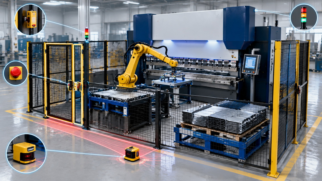
Safety cannot be added at the end of a robotic press brake project. It must be built into the cell design, operating modes, programming process, and daily management system.
In the United States, press brake safeguarding is commonly evaluated under OSHA's general machine-guarding requirements in 29 CFR 1910.212. ANSI B11.3 is widely used as the industry-specific safety reference for power press brakes, while ANSI B11.19 provides safeguarding performance criteria.
For robotic cells, ISO 10218 addresses safety requirements for industrial robots and robot applications. The standard emphasizes risk reduction, protective measures, and the information needed for safe use.
A well-designed robotic bending cell should address hazards during normal production, setup, fault recovery, maintenance, cleaning, and foreseeable misuse.
Key measures may include:
- Guard fencing and controlled access points.
- Interlocked gates and doors.
- Emergency-stop circuits located at accessible positions.
- Safety PLC or safety-rated control architecture.
- Laser scanners, light curtains, or other presence-sensing devices where appropriate.
- Press brake point-of-operation safeguarding.
- Robot speed and separation monitoring where applicable.
- Lockout/tagout procedures for maintenance.
- Clear reset procedures after a safety stop.
- Training for operators, programmers, maintenance staff, and supervisors.
- Documented risk assessment and safety validation records.
A risk assessment should evaluate the entire lifecycle of the cell—not just automatic production. This includes loading blanks, changing tools, clearing jams, recovering from faults, inspecting parts, and servicing the robot or press brake.
Practical recommendation: Require a documented acceptance checklist before production release. It should verify every interlock, E-stop, sensor, safe operating mode, restart behavior, robot program, and operator instruction.
A robot cell that performs one sample part during factory acceptance is not necessarily ready for production. Stable operation requires optimized bend sequencing, reliable gripping, collision avoidance, blank detection, error recovery, and handling of normal process variation.
Offline programming is valuable because it allows teams to prepare robot paths, check interference, and review tool arrangements before the cell is occupied. It can also reduce disruption when new programs are introduced.
1. Confirm the blank drawing, bend drawing, and revision status.
2. Verify actual material thickness, grain direction, surface condition, and blank dimensions.
3. Select tooling and define the bend sequence.
4. Create the robot handling path and gripper positions.
5. Simulate interference between robot, press brake, tooling, workpiece, and fixtures.
6. Run sample parts at controlled speed.
7. Check angle accuracy, flange dimensions, cosmetic quality, and stack stability.
8. Define alarm recovery procedures for double sheets, dropped parts, missed picks, and part misalignment.
9. Record approved parameters and revision-control the final program.
10. Monitor actual cycle time and quality during the first production batches.
For OEM and ODM projects, program discipline is particularly important. Engineering changes should be controlled so that revised tooling, part drawings, material specifications, and robot programs remain synchronized.
Automation changes the operator's role. Instead of manually positioning every part, the operator may manage loading, inspect output, respond to alarms, confirm quality, replenish material, and perform approved adjustments.
The strongest robotic bending teams combine experienced press brake knowledge with structured robot-cell training.
- Safe startup, shutdown, and restart procedures.
- Normal automatic operation and supervised manual modes.
- Safe access to the cell.
- Loading blanks and removing finished parts.
- Recognizing faulty blanks and handling surface-sensitive materials.
- Program selection and job verification.
- Basic alarm response and escalation rules.
- Daily inspections, cleaning, and approved preventive maintenance.
- Tooling identification and setup confirmation.
- Lockout/tagout awareness for maintenance work.
- Quality checks for first-off and in-process parts.
Training should be practical, role-specific, and documented. An operator does not need to become a robot programmer, but they should understand the limits of the cell and know when to stop production and request technical support.
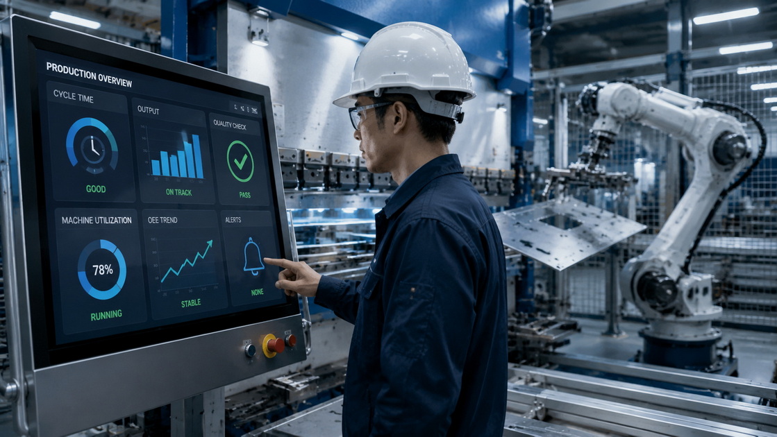
The first months after installation are the most important period for improvement. Measure actual results against the original business case, then use the data to improve the cell.
Focus on three performance areas:
| Performance area | What to measure | Why it matters |
|---|---|---|
| Availability | Downtime, alarm categories, recovery time, maintenance time | Reveals reliability and support needs |
| Performance | Actual versus planned cycle time, loading delays, idle time | Identifies handling and programming losses |
| Quality | First-pass yield, bend-angle variation, scratches, dropped parts, rework | Confirms whether automation is delivering stable output |
Track the top recurring stoppages. Common issues may include double-sheet picking, poor blank separation, inconsistent raw-material quality, insufficient gripper contact, bend-sequence interference, overloaded stacking areas, or incomplete operator procedures.
A structured continuous-improvement review can turn an acceptable robotic bending cell into a highly productive one. The goal is not merely to keep the robot moving. The goal is to produce conforming parts predictably and safely.
A press brake robot investment should match your parts, plant layout, staffing strategy, quality expectations, and future production plan. CNDY-Press supports manufacturers with CNC press brakes, sheet-metal equipment solutions, OEM and ODM manufacturing, customized configurations, application evaluation, and service support.
Whether you are automating a single repetitive product family or planning a connected sheet-metal production line, our engineering team can help assess your parts, recommend a suitable CNC press brake and robotic bending cell configuration, and develop a practical implementation plan.
The best candidates are repeatable sheet-metal parts with stable geometry, predictable bend sequences, manageable weight, and medium- to high-volume demand. Enclosures, brackets, cabinet components, HVAC parts, and appliance panels are common examples. Parts with highly variable blanks, frequent engineering changes, or severe handling interference may require additional engineering or may be better suited to manual bending.
In some cases, yes. Retrofit feasibility depends on the press brake's mechanical condition, controller compatibility, safety architecture, backgauge capability, tooling, available space, and ability to integrate with a robot and safety system. A new integrated press brake automation solution may provide stronger long-term reliability, but a technical evaluation is required before deciding.
The required area depends on machine length, robot reach, part size, loading method, safety fencing, finished-part stacking, and maintenance access. The space requirement is typically much larger than the footprint of a standalone CNC press brake because the entire robot work envelope and safeguarded area must be considered.
It can improve consistency by repeating programmed handling positions, bend sequences, and part orientation. However, final quality still depends on material consistency, blank accuracy, tooling condition, press brake calibration, crowning, bend-angle measurement, and correct programming. Automation improves repeatability; it does not eliminate the need for process control.
A properly engineered robotic bending cell can reduce exposure to repetitive manual handling and keep personnel outside hazardous zones during automatic operation. Safety depends on a documented risk assessment, correct safeguarding, validated safety devices, defined operating procedures, training, and regular inspection—not simply on the presence of a robot.
1. Occupational Safety and Health Administration. [29 CFR 1910.212 — General Requirements for All Machines]. Machine-guarding requirements relevant to press brake safeguarding.
2. The Fabricator. [Safeguarding Press Brakes Without Sacrificing Productivity]. Discussion of OSHA, ANSI B11.3, point-of-operation protection, active optoelectronic protective devices, and safe-speed safeguarding.
3. The Fabricator. [Know Your Press Brake Safeguarding Options]. Overview of ANSI B11.3, ANSI B11.19, machine control reliability, and risk assessment practices.
4. International Organization for Standardization. [ISO 10218-1:2025 — Robotics: Safety Requirements for Industrial Robots]. Requirements related to inherently safe industrial robot design, risk reduction, and information for use.
5. Association for Advancing Automation. [Updated ISO 10218: Major Advancements in Industrial Robot Safety Standards]. Context on ISO 10218 Parts 1 and 2 for industrial robots and robot cells.
6. Robotics Tomorrow. [Case Study: Robotic Press Brake—Automated Metal Bending]. Case-based discussion of productivity, extended operation, handling safety, and quality consistency benefits.
7. RBTX. [Press Brake Automation: Robotic Bending vs. Offline Programming]. Market-oriented discussion of robotic bending cell cost ranges, integration options, and payback considerations.


