


Views: 223 Author: CNDY-Press Publish Time: 2026-09-08 Origin: Site


Content Menu
● Why CNC Press Brake Errors Matter in Sheet Metal Manufacturing
● The Most Common CNC Press Brake Bending Problems
>> Cracking, Tearing, and Fractures at the Bend Line
>> Surface Marks, Die Lines, and Indentations
● Tooling and Setup Errors That Cause Defects
>> Incorrect Punch or V-Die Selection
>> Tool Wear, Galling, and Chipping
● Machine, Hydraulic, and CNC Control Problems
>> Ram Motion and Synchronization Errors
>> Backgauge Positioning Errors
>> Hydraulic Oil, Temperature, and Pressure Stability
● A Safer, More Repeatable Troubleshooting Process
● Press Brake Safety Must Never Be Bypassed
● Preventive Maintenance Checklist for CNC Press Brakes
● Work With CNDY-Press on Custom Press Brake Solutions
● FAQ
>> 1. What is the most common cause of inconsistent bend angles on a CNC press brake?
>> 2. How can I reduce springback in sheet metal bending?
>> 3. Why does sheet metal crack during press brake bending?
>> 4. Why is my press brake backgauge inaccurate?
>> 5. What preventive maintenance does a CNC press brake need?
A CNC press brake can produce highly repeatable sheet metal parts—but only when the machine, tooling, material, program, and operator setup work together as one controlled system. When bend angles drift, flanges vary, surfaces become damaged, or the ram moves irregularly, the correct response is not to "adjust until it looks right"; it is to trace the defect to its root cause.
At CNDY-Press, we work with OEM, ODM, and custom sheet metal fabrication requirements, where a small bending deviation can affect assembly fit, downstream welding, coating quality, and delivery schedules. This guide explains the most common CNC press brake operation errors, how to diagnose bending problems systematically, and how preventive maintenance, correct tooling, and smart CNC programming can reduce scrap and unplanned downtime.
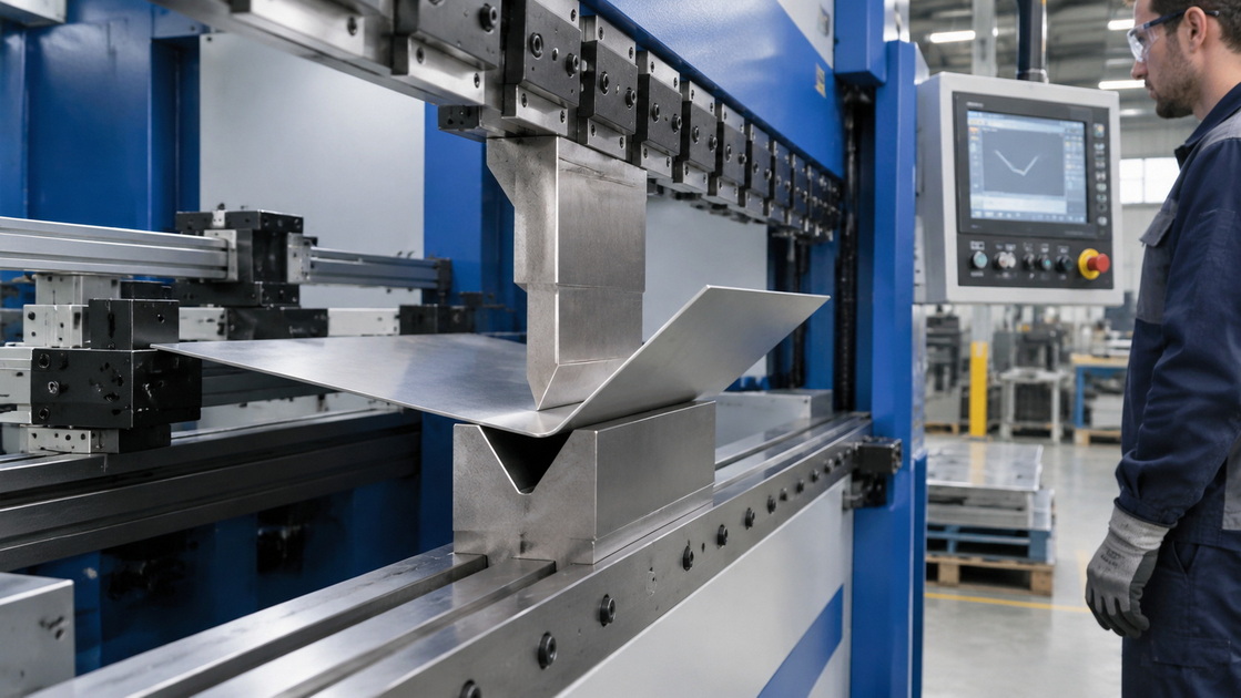
A press brake is not simply a machine that folds metal. It is a precision forming system. The final bend result depends on several connected variables:
- Material grade, thickness, temper, and grain direction
- Punch radius and V-die opening
- Bending method, such as air bending, bottoming, or coining
- Ram parallelism and crowning compensation
- Backgauge positioning accuracy
- Hydraulic pressure and oil condition
- CNC program parameters
- Operator setup discipline and first-piece inspection
When one variable changes, the part may no longer match the drawing. For example, a batch of 304 stainless steel that is slightly harder than the prior batch may produce more springback, even when the CNC program, tooling, and machine settings have not changed.
This is why successful sheet metal bending requires a process-control mindset, not just machine operation skills. The goal is to identify variation early, control it before it creates scrap, and record the correction so it can be repeated in future production.
Predictive maintenance follows the same principle: it uses observable conditions—such as temperature, vibration, noise, and machine behavior—to anticipate failure before it becomes a costly breakdown.
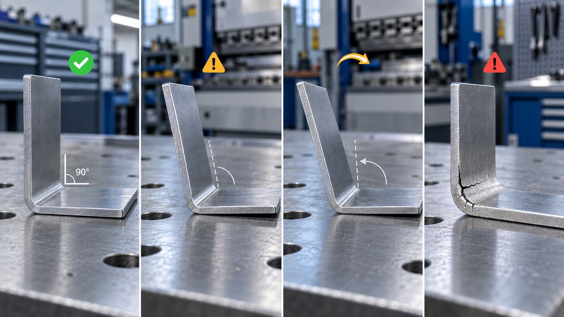
Inconsistent bend angles are among the most frequent press brake quality problems. A component may measure 90° at one end, 88° in the center, and 91° at the opposite end. This variation can cause poor assembly alignment, visible gaps, and rejected parts.
Common symptoms include:
- Bend angles vary from part to part.
- One side of a long bend is more open or closed than the other.
- The first part is acceptable, but later parts drift out of tolerance.
- The programmed angle does not match the actual formed angle.
| Possible root cause | Typical symptom | Recommended corrective action |
|---|---|---|
| Tool wear | Angle becomes less repeatable over time | Inspect punch tips and die shoulders; replace or regrind damaged tools |
| Material thickness variation | Different results from the same program | Confirm actual thickness and material certificates before production |
| Ram parallelism error | Different angles across a long workpiece | Check ram leveling, guide clearance, and synchronization |
| Missing crowning compensation | Center bend differs from end bends | Adjust mechanical or hydraulic crowning settings |
| Incorrect angle compensation | All parts consistently miss the target angle | Update the CNC bend allowance or angle correction value |
A practical first-piece inspection method is to measure the bend angle at the left end, center, and right end of the workpiece. If the difference is significant, do not immediately change the program. First inspect the machine alignment, tooling seating, material flatness, and crowning setting.
Springback occurs when sheet metal elastically recovers after the ram releases pressure. It is especially important in air bending, where the material does not fully conform to the die cavity.
High-strength steels, stainless steel, and hard-temper aluminum alloys generally show more springback than mild steel. The exact result depends on the material's yield strength, tensile strength, thickness, grain direction, bend radius, and tooling geometry.
For example, if a finished part requires a 90° angle but the material springs back by 3°, the machine may need to form the part to approximately 87° during bending. This is known as over-bending compensation.
Ways to control springback include:
- Use the actual material grade and thickness in the CNC program.
- Apply controlled angle correction after measuring the first piece.
- Choose a punch radius appropriate for the material.
- Use a narrower V-die opening when technically suitable.
- Consider bottoming or coining when tighter angle control is required.
- Keep material lots separated when their mechanical properties differ.
- Use automatic angle measurement systems for high-volume or tight-tolerance work.
The key is consistency. A correct compensation value for one batch of 304 stainless steel may not be correct for a different supplier, thickness tolerance, or temper condition.
Cracks at the outside surface of a bend usually indicate that the material has exceeded its forming limit. This is a serious quality concern because even a small crack can reduce fatigue life, corrosion resistance, and structural reliability.
The most common causes are:
- An inside bend radius that is too small.
- Bending across an unfavorable grain direction.
- Hard material temper or high-strength material grade.
- Incorrect punch radius.
- Damaged, rough, or contaminated tooling.
- Material defects or inconsistent mechanical properties.
- Excessive tonnage or improper bending method.
As a general manufacturing guideline, an inside bend radius near the sheet thickness—often expressed as 1T—is a reasonable starting point for many common mild steel, stainless steel, and formable aluminum applications. However, harder tempers and high-strength materials frequently require a larger radius. Material-specific rules should always be validated through a bend test, material data, and production inspection.
To reduce cracking risk:
1. Confirm the material grade, thickness, and temper before setup.
2. Use a bend radius appropriate for the specific material.
3. Avoid placing holes, slots, or notches too close to the bend line.
4. Bend across the grain direction when part geometry allows.
5. Inspect punch and die surfaces for chips, burrs, and sharp damage.
6. Run first-article bend tests before launching full production.
Surface damage can be unacceptable in architectural panels, appliance components, elevator parts, decorative stainless steel, painted sheets, and anodized aluminum. Even if the bend angle is correct, scratches and die marks may force rework or rejection.
Typical causes include:
- Dirty dies or punch surfaces.
- Metal chips trapped between the sheet and tooling.
- Galling caused by friction between the workpiece and die.
- Incorrect die opening or punch geometry.
- Unprotected bending of coated or polished material.
- Worn tooling edges.
- Excessive sliding during the bending cycle.
For sensitive surfaces, use a documented protection strategy:
- Clean tooling before each setup.
- Remove oil, chips, rust particles, and adhesive residue.
- Use protective film, urethane inserts, or non-marking die solutions where suitable.
- Store punch and die segments properly to prevent nicks and corrosion.
- Avoid dragging finished components across the die bed or support arms.
A well-maintained tooling library is not just a maintenance issue—it is a visible quality-control system.
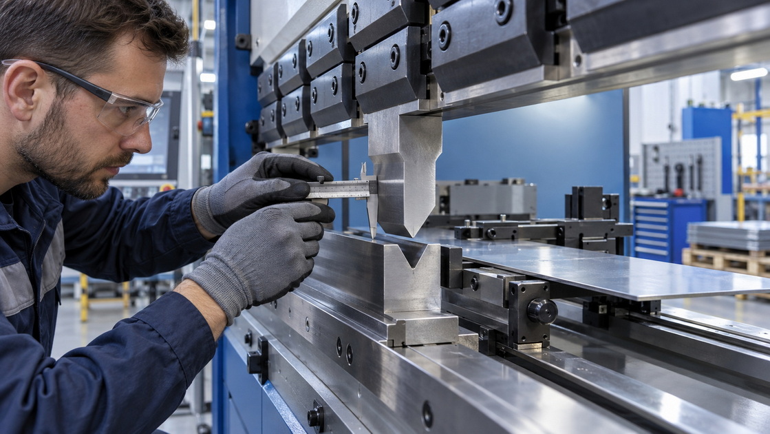
Tooling selection determines bending force, flange support, bend radius, surface quality, and achievable geometry. Using the wrong V-die opening can create angle inconsistency, excessive marking, cracking, or overload conditions.
A die opening that is too narrow may require excessive tonnage and increase the risk of tool or machine damage. A die opening that is too wide can create poor angle control, wider internal radii, and increased springback.
Before each setup, confirm:
- Material type and thickness.
- Required inside bend radius.
- Target angle and tolerance.
- Bending method.
- Punch tip radius.
- V-die opening.
- Minimum flange length.
- Total bend length.
- Required tonnage.
- Need for crowning or workpiece support.
Do not rely only on a previous setup record. Review the current job drawing, material batch, program revision, and tooling condition.
Misaligned tooling can produce uneven angles, surface damage, tool chipping, and abnormal noise. In severe cases, punch-to-die interference can damage expensive tooling and place excessive load on the ram and hydraulic system.
Signs of misalignment include:
- A visible offset between punch and die centerlines.
- Uneven tool contact along the bed.
- Repeated tool chipping at one location.
- Bends that are tighter on one side.
- Unusual impact noise during the forming stroke.
The correct procedure is to stop production, secure the machine according to the manufacturer's safety procedure, inspect tool seating, verify clamping, and re-establish alignment. Never attempt to "correct" major alignment problems by changing only the CNC angle parameter.
Tool wear is often gradual, which makes it easy to overlook. A punch tip may become rounded, die shoulders may wear unevenly, or galling may create rough contact surfaces. These defects transfer directly to the workpiece.
Implement a practical tooling inspection routine:
| Inspection frequency | What to check | Why it matters |
|---|---|---|
| Daily | Cleanliness, chips, rust, visible damage | Prevents marks and setup-related defects |
| Weekly | Punch tips, die shoulders, clamping surfaces | Identifies early wear and alignment risks |
| Monthly | Tool identification, storage condition, repeated defect history | Improves traceability and reduces setup time |
| Before high-volume jobs | Tool geometry, matching segments, load capacity | Avoids interruption during production |
The ram must move smoothly through approach, forming, dwell, and return. Hesitation, vibration, uneven descent, or drift can point to mechanical, hydraulic, electrical, or feedback-control issues.
Watch for these warning signs:
- Jerky ram movement.
- One side of the ram descending faster than the other.
- Excessive vibration during slow bending speed.
- Ram drift when the machine is stopped.
- Delayed return stroke.
- Unusual hydraulic noise.
- Repeated synchronization alarms.
Potential root causes include contaminated hydraulic oil, trapped air, leaking cylinder seals, faulty proportional valves, worn ram guides, encoder errors, or incorrect CNC synchronization parameters.
Because press brake motion is safety-critical, operators should not attempt unauthorized hydraulic or electrical repairs. Use trained maintenance personnel and follow the machine manufacturer's service procedure.
The backgauge controls flange length and bend location. A small backgauge error can make an entire batch unusable, particularly when multiple bends must align during final assembly.
Common symptoms:
- Flanges are too long or too short.
- Dimensions vary from part to part.
- The backgauge makes unusual noise or moves unevenly.
- Parts shift during positioning.
- The same program produces inconsistent bend locations.
Check for backlash, loose fasteners, worn drive components, contamination on guide rails, encoder or servo issues, and incorrect calibration. After maintenance, verify the backgauge using a calibrated measurement method before production resumes.
Hydraulic oil is both a working fluid and a diagnostic signal. Poor oil cleanliness, low oil level, overheating, leaks, or pressure instability can affect ram control and shorten component life.
A disciplined hydraulic maintenance plan should include:
- Inspecting for visible leaks at hoses, cylinders, fittings, and valves.
- Monitoring oil temperature during extended operation.
- Replacing filters on schedule.
- Testing hydraulic oil condition according to the equipment manufacturer's recommendations.
- Investigating sudden pressure drops immediately.
- Keeping the hydraulic system clean during service work.
Predictive maintenance programs often use operational data such as temperature, vibration, and noise to identify developing issues before a full machine failure occurs.
When a bending defect occurs, avoid making several random parameter changes at once. That approach hides the actual cause and makes future setups harder to repeat.
Use this structured troubleshooting process instead:
1. Stop and define the defect. Record the actual measurement, location, material, tool set, program number, and machine condition.
2. Separate part defects from machine faults. Determine whether the issue is angle, position, surface finish, cracking, distortion, or ram behavior.
3. Inspect the simplest variables first. Check material thickness, material orientation, tool cleanliness, tool selection, and setup alignment.
4. Measure the first piece accurately. Confirm bend angle, flange length, diagonal dimensions, and part flatness.
5. Make one controlled adjustment. Change only one parameter at a time, such as angle compensation or backgauge offset.
6. Verify and document the result. Save validated settings, tooling details, material information, and inspection results for repeat jobs.
7. Escalate safety-related faults. Stop operation and contact qualified technicians for hydraulic leaks, unusual ram behavior, electrical alarms, damaged guarding, or suspected control failures.
This method creates a reusable knowledge base for OEM and ODM projects, where repeatability, traceability, and fast setup are often essential to profitability.
Quality and safety are inseparable. A machine that is producing inaccurate bends may also be signaling a safety problem, especially when ram motion, pressure control, electrical feedback, or tooling alignment is abnormal.
OSHA's machine-guarding requirements require employers to use one or more safeguarding methods to protect employees from hazards associated with machine operation. For powered press brakes, appropriate protective measures may include physical barriers, safeguarding devices, restricted access, and documented procedures.
Important safety practices include:
- Never bypass light curtains, safety devices, interlocks, or emergency stops.
- Use lockout/tagout procedures during maintenance and servicing.
- Support the ram mechanically before working in a hazardous position.
- Keep hands and body parts away from the point of operation.
- Train operators on job-specific setup, tooling, and emergency procedures.
- Stop the machine immediately when repeated alarms, abnormal movement, or unsafe conditions occur.
Safety systems should be treated as essential production equipment—not as obstacles to speed.

A simple maintenance routine can prevent many common press brake operation errors before they affect production.
| Frequency | Recommended maintenance task |
|---|---|
| Before each shift | Check guarding, emergency stops, oil level, visible leaks, tooling condition, and work area cleanliness |
| Daily | Clean punch and die surfaces; remove chips and debris; inspect for unusual noises or vibration |
| Weekly | Inspect clamping, tool alignment, ram guides, backgauge movement, hoses, and fittings |
| Monthly | Verify backgauge calibration, inspect filters, review recurring alarm history, and lubricate designated points |
| Scheduled service interval | Test oil condition, replace filters or fluid as required, inspect cylinders and valves, and confirm machine accuracy |
| After tool or material change | Conduct first-piece inspection and confirm bend angle, flange dimension, and surface condition |
For custom sheet metal production, we also recommend maintaining a job record that includes the material supplier, thickness, tool combination, die opening, punch radius, bending sequence, angle correction, crowning setting, and inspection result. This record reduces setup time and improves consistency when the job repeats.
The most reliable way to reduce bending errors is to combine the right machine configuration, tooling strategy, CNC control capability, operator training, and maintenance support.
CNDY-Press provides CNC press brakes and integrated sheet metal fabrication equipment for manufacturers, OEM customers, ODM partners, and customized production projects. Whether you need a machine for thin-gauge precision parts, long-bed bending, high-tonnage applications, complex multi-bend workpieces, or automated material handling, the right configuration should be selected around your material, part geometry, tolerance, output target, and workflow.
The most common causes are material variation, incorrect angle compensation, worn tooling, ram alignment problems, and insufficient crowning compensation. Start by measuring the bend at the left, center, and right sides of the part, then inspect tooling and material before changing the CNC program.
You can reduce springback by applying controlled over-bending, selecting an appropriate punch radius and V-die opening, using bottoming when suitable, and verifying the actual material grade and thickness. Automatic angle measurement systems can also improve repeatability in high-volume production.
Cracking usually occurs when the bend radius is too tight for the material, the material is hard or brittle, the grain direction is unfavorable, or tooling surfaces are damaged. Increasing the inside bend radius and performing a first-piece bend test are effective preventive measures.
Backgauge inaccuracy may result from mechanical backlash, worn drive components, loose fasteners, rail contamination, servo or encoder faults, or calibration drift. Inspect the mechanical system first, then recalibrate and verify the position with a measured test part.
Routine maintenance should include cleaning tooling, checking for hydraulic leaks, inspecting ram movement, monitoring oil condition and temperature, verifying backgauge calibration, lubricating designated points, and reviewing recurring CNC alarms. The exact schedule should follow the machine manufacturer's maintenance manual.
1. [CNDY-Press / HAWE, "A Deep Dive into Press Brake Operation Errors: Common Bending Problems, Symptoms and Solutions"] — Source material reviewed and substantially restructured for this article. [cnhawe]
2. [National Institute of Standards and Technology (NIST), "Manufacturing Machinery Maintenance"] — Background on predictive and condition-based maintenance using measurable operating conditions. [nist]
3. [Occupational Safety and Health Administration (OSHA), "Guidelines for Point of Operation Guarding of Power Press Brakes"] — Guidance on power press brake guarding, trained operators, safe-distance procedures, and hazardous-energy controls. [osha]
4. [Occupational Safety and Health Administration (OSHA), "Power Press Brakes"] — Interpretation of applicable point-of-operation safeguarding requirements. [osha]
5. [OSHA eTool, "Machine Guarding: Powered Press Brakes"] — Safety resource for powered press brake hazards and guarding considerations. [osha]
6. [American Institute of Steel Construction, "Development of Fabrication Guidelines for Cold Bending of Steel Plates"] — Technical reference on cold-bending considerations and minimum inside bend radii. [ej.aisc]
7. [Protolabs, "The Basics of Bend Radii in Sheet Metal"] — Practical discussion of bend-radius selection in sheet metal design and fabrication. [protolabs]


