


Views: 238 Author: CNDY-Press Publish Time: 2026-09-20 Origin: Site


Content Menu
● Why Scratch-Free Sheet Metal Bending Matters
● Where Scratches Actually Come From
● Tip 1: Use Clean, Smooth, Application-Specific Tooling
>> Inspect the Entire Tooling Path
>> Match Tooling to the Material
● Tip 2: Use Urethane Die Film or Non-Marring Tooling
>> When Protective Film Is Most Useful
>> Film Is Not a Universal Fix
● Tip 3: Select the Right Punch Radius and V-Die Opening
>> Why Die Selection Affects Surface Quality
>> A Simple Engineering Principle
● Tip 4: Control Sheet Handling Before, During, and After Bending
● Tip 5: Optimize CNC Press Brake Parameters
>> Avoid the "Maximum Speed" Mistake
● Tip 6: Build a Surface-Quality Inspection System
>> Define What Counts as a Defect
>> Use a Practical Inspection Routine
● Tip 7: Maintain Tooling, Supports, and the Work Environment
>> Daily Surface-Protection Checklist
>> Safety Must Remain Non-Negotiable
● A Surface-Safe Bending Workflow for OEM Production
● How CNDY-Press Supports Surface-Critical Bending Projects
>> 1. Why does my press brake leave lines on stainless steel?
>> 2. Can urethane die film change bend angle?
>> 3. What is the best way to bend powder-coated sheet metal without scratching it?
>> 4. How can I prevent aluminum from leaving black marks on press brake tools?
>> 5. Are scratch-free bending tools necessary for every part?
Scratch-free sheet metal bending is a controlled manufacturing process—not a matter of slowing down the press brake or asking operators to "be careful." When bending stainless steel, aluminum, painted sheet, powder-coated panels, brushed metal, galvanized sheet, or decorative laminates, surface defects can trigger rework, rejection, coating repair, corrosion risk, and avoidable delivery delays.
For fabrication managers and OEM buyers, the objective is clear: achieve the required bend angle and flange dimension without damaging the visible surface. That requires the correct press brake tooling, protective barriers, material-handling process, CNC parameters, inspection standards, and operator safety controls.
At CNDY-Press, we manufacture CNC press brakes and complete sheet metal fabrication equipment for OEM, ODM, and customized production projects. This guide explains how to bend sheet metal without scratches and how to build a repeatable, surface-protection process around your actual material, part geometry, batch size, and quality requirements.
Quick answer: Most press brake scratches come from metal-to-metal sliding contact, worn or contaminated tooling, incorrect die selection, unsupported material movement, or poor handling after the bend. The most effective solution is to control all five—not just add protective film after defects appear.

A scratch on hidden structural steel may be a cosmetic issue. A scratch on brushed stainless steel, anodized aluminum, polished aluminum, painted sheet, powder-coated material, or appliance-grade panels can be a rejection issue.
Surface damage can create:
- Visible scratches and die marks
- Galling and material pickup
- Coating cracks or delamination
- Reduced corrosion resistance at damaged areas
- Inconsistent appearance between parts
- Extra polishing, repainting, or refinishing work
- Customer complaints and warranty claims
- Higher scrap and rework costs
- Delays in assembly and shipment
Surface quality is part of functional quality. In food-service equipment, medical enclosures, elevators, architectural panels, consumer appliances, electronics cabinets, and premium industrial equipment, the final surface often affects customer acceptance as much as dimensional tolerance.
The source article usefully identifies tooling selection, protective film, bending parameters, material handling, advanced tools, process monitoring, and CNC features as the major areas to control. The deeper issue is that scratch prevention should be treated as a documented process standard, not seven separate shop-floor tips.
Before changing tooling or buying film, identify the location and pattern of the damage. The scratch pattern often reveals the root cause.
| Surface Defect Pattern | Likely Cause | First Action |
|---|---|---|
| Straight marks parallel to bend line | Lower die shoulder contact, burrs, or die contamination | Inspect and clean the V-die shoulders |
| Random fine scratches across sheet | Dirty worktable, support arms, rollers, or handling contact | Clean all contact surfaces and review material flow |
| Repeated marks at the same location | Tooling nick, damaged coating, or sharp edge | Polish, repair, or replace the damaged tool |
| Dark streaks on aluminum | Material pickup or galling on tools | Clean tooling and use suitable low-friction protection |
| Scratches near backgauge contact points | Backgauge fingers or sheet sliding during positioning | Inspect finger condition and use suitable protective interfaces |
| Marks on painted or powder-coated sheet | Direct steel-tool contact or excessive contact pressure | Use non-marring tooling, film, or protective die covers |
| Scuffs after the bend | Parts rubbing on the bed, floor, carts, or stacked parts | Improve post-bend handling and part separation |
A scratch-free process begins with evidence. Take photos, note material type, thickness, tooling set, bend direction, operator, press-brake program, and the stage at which damage first appears. This turns a vague quality complaint into a correctable process problem.

Tooling is the first contact point between the press brake and the part. If the punch, V-die, clamps, backgauge fingers, or support surfaces are dirty, nicked, rusted, worn, or poorly finished, the part can be damaged even when the CNC program is correct.
Before bending surface-critical material, inspect:
- Punch tip and shoulders
- V-die shoulders and V-opening
- Tool-clamping surfaces
- Die holders and adapters
- Backgauge fingers
- Front supports
- Brush tables, rollers, or ball transfers
- Sheet-lifting devices
- Worktable and staging racks
Pay special attention to the V-die shoulders. In air bending, the sheet slides and rotates over these shoulders as the punch descends. A small burr, embedded metal fragment, or hardened material pickup can leave a repeatable line across every part.
| Material | Main Surface Risk | Recommended Starting Strategy |
|---|---|---|
| Brushed stainless steel | Scratching, directional finish damage, galling | Polished tooling, clean die shoulders, protective film, controlled handling |
| Mirror stainless steel | Fine scratches and pressure marks | Protective film, non-marring tooling, dedicated clean workstation |
| Aluminum | Galling and black transfer marks | Clean low-friction tools, protective die film, dedicated aluminum tooling if possible |
| Painted sheet | Coating damage and cracks | Urethane protection, suitable punch radius, reduced sliding contact |
| Powder-coated sheet | Chipping, pressure marks, and scuffing | Non-marring die covers, controlled tonnage, soft supports |
| Galvanized steel | Zinc pickup and visible rubbing | Clean tooling, correct V opening, surface protection when appearance matters |
| Decorative laminate sheet | Irreversible face damage | Film, urethane tooling, careful part support, validated test bends |
Best practice: Separate tooling used for stainless steel and aluminum from tooling used on abrasive or dirty materials whenever practical. Cross-contamination can transfer particles and create scratches that are difficult to trace later.
For visible surfaces, the most direct method of preventing die marks is to place a protective barrier between the workpiece and the lower die.
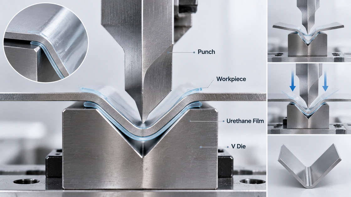
A common option is urethane press brake die film, also called anti-marking film, no-mar film, die protection film, or polyurethane die film. It is positioned on top of the lower V-die so the sheet does not touch the steel die shoulders during positioning or bending.
Mate Precision Technologies explains that anti-scratch polyurethane film is placed on the lower die and protects the material while it is positioned, against backgauge contact, and during the bend; the part does not directly contact the die.
Use protective film or a urethane-based system for:
- Brushed or mirror-finish stainless steel
- Painted or powder-coated sheet
- Anodized aluminum
- Polished aluminum
- Pre-finished appliance panels
- Decorative sheet metal
- High-value, low-volume parts
- Prototype and first-article production
- Parts that would be expensive to refinish
Protective film can reduce marking, but it changes the bending condition. It may affect the effective die opening, bend radius, angle, springback response, and required ram depth.
Before release to production:
1. Install the film consistently.
2. Make test bends with the actual production material.
3. Measure bend angle and flange dimension.
4. Adjust the CNC program if necessary.
5. Inspect both the visible face and bend exterior.
6. Record the film type and thickness in the setup sheet.
Do not let operators substitute a random plastic sheet, cardboard, tape, or worn film. Use a defined material and replacement standard. Urethane die film is marketed specifically to prevent die marks, cross-metal contamination, and scratches on painted, aluminum, stainless, and polished stock.
Depending on part geometry and volume, consider:
- Urethane die inserts
- Nylon or polymer V-die inserts
- Rotary or rolling bending tools
- Brass or bronze contact components where suitable
- Coated punches and dies
- Dedicated non-marring tool sets
- Protective factory film left on the sheet face, where bend validation allows
- Custom soft-contact fixtures
For high-volume parts, a dedicated non-marring tooling solution may cost more initially but can reduce film replacement, operator variation, and surface-related scrap.
A scratch-free bend depends on the contact pressure between the workpiece and the tooling. Tool geometry directly affects this pressure.
A V-die opening that is too narrow can increase forming force, intensify contact pressure on the die shoulders, create excessive sliding, and make surface marking more likely. An unsuitable punch radius can also concentrate stress at the bend line, increasing the risk of coating cracks or inconsistent results.
For air bending, a common starting rule for mild steel is a V-opening near 8 × material thickness, but this is not a universal formula. Material grade, tensile strength, finish, required inside radius, bend length, and finished-part specification must be considered. Tooling suppliers publish air-bending force charts that relate material, die opening, bend length, and required tonnage.
- Use the largest V-opening that still achieves the required inside radius and flange geometry.
- Avoid sharp die edges on cosmetic materials.
- Choose a punch radius that suits the material and coating.
- Use clean, polished tooling for appearance-critical work.
- Avoid mixing worn and new die segments in one long bend.
- Confirm the tool profile does not force finished flanges to drag against the punch or die during part removal.
- Use a gooseneck punch when return flanges would otherwise contact the tool.
Higher contact pressure and more sliding generally increase the risk of marks. The goal is not always "use the softest tooling." The goal is to use a stable, validated tool setup that forms the required geometry with the least damaging contact.
Many surface defects are not made by the punch or die. They occur when sheets are dragged across dirty supports, rubbed against metal tables, stacked face-to-face, or moved without adequate support.
- Store finished sheet away from grinding, welding, and abrasive operations.
- Keep protective factory film intact where possible.
- Use clean gloves suitable for the material and finish.
- Remove sharp offcuts and metal chips from the work area.
- Inspect material for pre-existing defects before forming.
- Use non-marring carts, racks, or protective separators.
- Lift sheets rather than dragging them over die shoulders and supports.
- Use brush tables, coated rollers, ball transfers, or soft-contact support arms where appropriate.
- For large panels, use sheet followers, front supports, vacuum lifters, or two-person handling.
- Keep backgauge fingers clean and free from sharp edges.
- Avoid allowing a heavy sheet to pivot and scrape across the machine bed.
- Ensure formed flanges do not rub against tooling during repositioning.
- Place parts on padded racks, foam separators, felt-lined carts, or clean protective sheets.
- Do not stack cosmetic faces directly against each other.
- Separate parts with non-abrasive interleaving material.
- Protect sharp edges to prevent them from scratching adjacent parts.
- Keep completed surface-critical parts away from welding, grinding, and forklift traffic.
Expert insight: For large stainless-steel panels, the highest scratch risk is often the second or third bend—not the first. After one flange is formed, the part becomes harder to support and may rub against the machine bed, backgauge, tooling, or another flange. Plan the bend sequence around the part's changing center of gravity and contact points.
Correct tooling still needs correct machine settings. Excessive speed, over-tonnage, unsuitable ram depth, poor bend sequencing, or uncalibrated crowning can increase pressure, sliding, and visible marks.
| Parameter | Surface-Quality Impact | What To Check |
|---|---|---|
| Approach speed | High impact may increase sliding and shock | Reduce if needed for delicate materials |
| Bending speed | Controls forming dynamics | Validate on the specific material and coating |
| Return speed | Can affect part stability and operator handling | Use a controlled, safe return sequence |
| Ram depth | Overbending can increase pressure and surface contact | Calibrate with test bends |
| Tonnage limit | Excess force can deepen marks and damage coatings | Use the lowest reliable force |
| Crowning | Uneven load can create inconsistent marks along long bends | Check long-part results |
| Backgauge position | Incorrect positioning can cause scraping and poor handling | Inspect contact points |
| Bend sequence | Poor sequence can make flanges hit tooling or supports | Simulate and validate before production |
Modern CNC systems can store material and tooling libraries, bend sequences, and correction values. Use those features to standardize a proven process, but ensure that the operator confirms material thickness and batch condition before running production.
The fastest cycle is not always the most productive cycle. If high approach or bending speed creates scratches, handling instability, or part movement, it can generate rework that eliminates any cycle-time advantage.
For cosmetic parts, measure performance by:
- Good parts per hour
- Surface-defect rate
- Rework time
- Film consumption
- Tool-cleaning time
- First-pass yield
- Customer rejection rate
This provides a more useful production metric than ram speed alone.

A scratch-free process must be verified, not assumed. Visual inspection is necessary, but the lighting condition and acceptance standard must be consistent.
Before production, agree on:
- Viewing distance
- Viewing angle
- Light intensity and color temperature
- Which surface is cosmetic or customer-visible
- Acceptable scratch length, width, and depth
- Acceptable die-mark visibility
- Coating crack criteria
- Inspection sampling plan
- Repair and disposition rules
A superficial mark may be acceptable on an internal mounting flange but unacceptable on a front-facing elevator panel. The same component can therefore require different inspection criteria by surface zone.
1. Inspect the first-off part under controlled lighting.
2. Confirm bend angle, flange dimension, and surface condition.
3. Approve the sample against the golden sample or visual standard.
4. Check at defined intervals during production.
5. Inspect after material-coil or sheet-batch changes.
6. Stop and investigate repeated marks immediately.
7. Document root causes and corrective actions.
For critical programs, use structured lighting, high-resolution cameras, or machine-vision systems to improve repeatability. However, technology does not replace a clear visual standard and trained quality personnel.
Surface quality declines gradually when maintenance is reactive. A damaged die, worn brush strip, dirty roller, or rusted support can create a scratch pattern long before the issue is noticed.
- Clean punch and die surfaces with a non-abrasive, approved method.
- Remove metal chips, adhesive residue, and material pickup.
- Check die shoulders for dents, nicks, corrosion, and sharp edges.
- Inspect backgauge fingers and support arms.
- Check roller tables, ball transfers, brushes, and carts.
- Verify that protective film is clean, properly positioned, and not worn through.
- Inspect clamps and tooling alignment.
- Remove loose fasteners, damaged tools, and offcuts from the work area.
- Confirm safety devices are operational before production.
Scratch prevention must never lead an operator to bypass a safety device, reach into a hazardous area, or use an unsafe handling method.
OSHA describes powered press brakes as machines used mainly for bending and forming sheet metal with dies attached to a ram and bed. Its machine-guarding guidance requires safeguarding methods that prevent employees from entering danger zones during the operating cycle.
Use appropriate safeguards, training, lockout/tagout procedures for maintenance, correct lifting equipment, and safe work practices. Surface-quality improvements should support safety—not compete with it.
For OEM and ODM production, surface protection should be built into the process plan from the RFQ stage.
1. Identify cosmetic surfaces on drawings using clear labels or visual zones.
2. Define material, coating, grain direction, and protective-film condition.
3. Select tooling based on geometry, material, bend radius, and finish requirements.
4. Conduct test bends using production-grade material.
5. Choose protective film or non-marring tooling where direct die contact could damage the surface.
6. Optimize the CNC program for ram depth, speed, tonnage, crowning, and bend sequence.
7. Approve a golden sample under agreed lighting and inspection conditions.
8. Train operators on lifting, positioning, support, and post-bend separation.
9. Run a pilot batch and monitor defect patterns.
10. Lock the process with setup sheets, tool IDs, film specification, and inspection records.
This workflow is especially valuable for stainless-steel cabinets, electrical enclosures, elevator parts, appliance panels, architectural components, medical equipment housings, and decorative metal products.
CNDY-Press develops, manufactures, sells, and services CNC press brakes and complete sheet metal processing equipment. For customers producing surface-sensitive parts, the right machine configuration should be considered alongside the complete bending process.
A customized CNC press brake project may include:
- Appropriate tonnage and bending length
- Hydraulic, servo-hydraulic, or electric-drive configuration
- CNC controller and tooling database selection
- Multi-axis backgauge configuration
- Automatic crowning system
- Tool-clamping system
- Front support arms and sheet followers
- Laser or other safeguarding configuration
- Tooling recommendations for material and finish
- Customized throat depth, stroke, daylight, and table configuration
- OEM branding, color, interfaces, and export packaging
The most common causes are dirty or damaged lower-die shoulders, direct steel-to-sheet contact, embedded particles, improper die selection, material pickup, or sheet sliding during handling. First inspect the tooling and support surfaces, then test a clean setup with protective die film or a non-marring die solution.
Yes. Protective film adds a layer between the sheet and lower die, changing contact conditions and potentially affecting bend angle, inside radius, and springback. Always make test bends with the exact film type and thickness used in production, then adjust ram depth or program corrections as needed.
Use clean, polished tooling; a suitable punch radius and V-die opening; urethane protective film or non-marring die inserts; gentle sheet handling; padded support and storage surfaces; and validated CNC settings. Also confirm that the coating can tolerate the target bend radius without cracking.
Aluminum can gall or transfer material to tooling, creating marks on later parts. Clean the punch and die regularly, avoid cross-contamination, use low-friction protective film or coatings, and consider dedicated tooling for sensitive aluminum work. Inspect die shoulders for aluminum buildup before each run.
No. They are most valuable for visible, coated, polished, anodized, brushed, or high-value parts where refinishing costs exceed the added tooling and setup cost. For hidden structural components, standard well-maintained tooling may be sufficient. The decision should be based on customer acceptance criteria and total cost of quality.
1. CNHAWE. "[How to Bend Sheet Metal Without Scratches: 7 Press Brake Operation Tips]." Original article reviewed and expanded for this guide; source for the initial seven-topic framework covering tooling, protective film, machine settings, handling, advanced tooling, quality monitoring, and CNC features. [cnhawe]
2. Mate Precision Technologies. "[Eliminate Die Marks and Scratches]." Source describing polyurethane anti-scratch film positioned over the lower die to protect sheet surfaces during positioning and bending. [mate]
3. Punch Tools. "[Press Brake Urethane Protection Die Film]." Source describing die film as a way to prevent die marks, cross-metal contamination, and tool marks on painted metals, aluminum, stainless steel, and polished materials. [punchtools]
4. Poly Products. "[Protective Press Brake Die Film]." Source describing urethane die cover film for preventing die marks and protecting painted, aluminum, stainless-steel, and polished surfaces. [polyprod]
5. Acrotech. "[Acro Hyde Urethane Die Film]." Source describing urethane die film placement on the lower die and its use in preventing marks on painted, stainless, aluminum, and polished materials. [acrotechinc]
6. Occupational Safety and Health Administration. "[Powered Press Brakes]." Source defining powered press brakes as metalworking machines that form parts using dies on a ram and bed. [osha]
7. Occupational Safety and Health Administration. "[General Requirements for All Machines, as Applied to Power Press Brakes]." Source for general machine-guarding requirements that protect employees from danger zones during operating cycles. [osha]
8. AMADA. "[Combination of Dies and Punches]." Technical reference containing air-bending-force chart information for press-brake tooling and mild-steel bending conditions. [amada]
9. JSTMT. "[Press Brake Tonnage Chart: Tons Per Meter for Air Bending]." Reference for V-die selection starting points, tonnage factors, and air-bending calculation context. [jstmt]


